The general operating function of this valve is identical to the thermostatic expansion valve (internally equalised) covered in last month’s article in that refrigerant flow to the evaporator is continuously regulated in accordance with thermal load changes on the evaporator.
Modulation of refrigerant flow in both types of valve is controlled by maintaining a constant superheat setting at the outlet of the evaporator coil.
If the evaporator coil is constructed from a substantial length of tube and/or small internal tube diameter, a substantial pressure drop between the inlet and outlet will result. All evaporators experience a pressure drop. However, if this is excessive, the saturation temperature of the refrigerant at the evaporator outlet will be considerably lower than the saturation temperature at the inlet due to the differences in pressure. Under these circumstances, an increase in the amount of superheat is required to produce a condition of equilibrium at the expansion valve diaphragm and this can only be achieved by allocating more of the evaporator coil surface to producing superheated vapour. Increased superheat within the evaporator reduces capacity since a lower amount of liquid refrigerant will be vaporised.
The effects of severe pressure drop can be offset by using an externally equalised thermostatic expansion valve. In this type of valve, the underside of the diaphragm is isolated from the evaporator inlet pressure. An external equaliser line connects the underside of the diaphragm to the outlet of the evaporator instead, thus ensuring that the superheat measured by the phial (bulb) relates correctly to the saturation temperature and pressure at the evaporator outlet. The external equaliser cannot reduce the pressure drop experienced through the evaporator coil but ensures that the coil area is fully utilised for effective evaporation of liquid thereby maintaining high system capacity and efficiency.
A schematic drawing of the externally equalised thermostatic expansion valve is shown in Fig 1 (overleaf). Compare this to the thermostatic expansion valve (internally equalised) shown in last month’s article. The pressure drop through the evaporator is 0.9bar resulting in a reduction in saturation temperature for refrigerant R22 of 5K (5°C - 0°C).
The external equalisation line reads the lower pressure at the evaporator outlet (3.9bar and 0°C saturation temperature) and transfers this to the underside of the diaphragm. The bulb senses a leaving coil temperature of 7°C (7K superheat) and the refrigerant charge develops a pressure in the bulb and over the diaphragm of 5.2bar.
If an external equalising line had not been used, a pressure of 4.8bar instead of 3.9bar would be exerted on the underside of the diaphragm. More superheat (12K instead of 7K) would then be required to develop sufficient pressure in the bulb to open the valve with a subsequent reduction in evaporator and system capacity and efficiency.

Figure 1: Schematic of an externally equalised thermostatic expansion valve
Construction
The construction of a typical thermostatic expansion valve can consist of the following: diaphragm housing, capillary and phial, which can be constructed from stainless steel and the valve body from brass. The capillary tube is often the most vulnerable part of the valve as it is often subject to vibration and flexing. The use of stainless steel would eliminate this weakness. The same philosophy can be applied to small pipes connecting statically-mounted HP and LP (high and low pressure) switches to vibrating parts of refrigeration circuits. This is particularly critical on large installations with a large refrigerant charge where such a fracture could lead to product stock losses and substantial release of refrigerant to atmosphere resulting in either stratospheric ozone depletion and/or global warming. The illustrations in Fig 2 below simplify the theoretical principles behind the internally and externally equalised thermostatic expansion valve:
Pb = bulb pressure (downward)
Pe = evaporating pressure (upward) (at evaporator inlet or outlet according to valve type)
Ps = spring pressure (upward)
Compressor protection
Thermostatic expansion valves maintain a given superheat in accordance with the spring pressure setting irrespective of evaporator pressure and loading. This key feature also has the disadvantage of allowing the compressor to become overloaded as a result of too high a pressure and entering gas temperature under peak load conditions. When the air conditioning system is first started, the temperature and therefore pressure in the bulb may be quite high. This causes the expansion valve to be partially or fully open when the compressor is started. This can lead to liquid flooding and damage to the compressor, particularly if the suction line is short or if the system is over-charged with refrigerant.
As the evaporating pressure and temperature drop, the expansion valve begins to regain control. Even under normal running conditions, the load at start-up may be substantial and this is particularly true of pull-down situations in refrigeration applications where the evaporator pressure and temperature are well above normally acceptable limits. Whilst it can be argued that a larger compressor will deal with this situation, a cheaper solution can be found in the selection of the correct expansion valve unless rapid pull-down to the desired temperature is essential.
Many expansion valves are fitted with a pressure-limiting feature (maximum operating pressure - MOP), which modulates the flow of refrigerant through the valve when the evaporating pressure rises above a pre-set level, irrespective of the bulb pressure and action of the diaphragm on the needle valve. This solves both of the aforementioned problems.
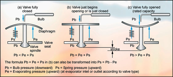
Figure 2: Theoretical principles behind the internally and externally equalised thermostatic expansion valve
Maximum operating pressure (MOP)
This defines the level of the pressure-limiting characteristic of the expansion valve. This pressure-limiting feature can be achieved by use of a spring positioned between the diaphragm and the needle valve stem, which opposes the action of the bulb. Certain types of valve allow adjustment of this spring pressure.
An alternative method utilises a collapsible chamber (cartridge), which is positioned between the diaphragm and the valve stem. The cartridge is filled with a non-condensable gas, which virtually remains at constant pressure regardless of temperature changes. The cartridge transmits the pressure exerted by the bulb directly to the diaphragm. If the evaporator pressure below the diaphragm becomes too high, this will overcome the pressure in the cartridge and the valve will tend to close. When the evaporator pressure falls below the pressure of the gas in the cartridge, the cartridge expands to the original size, transmits normal bulb pressure to the diaphragm and control of the valve returns to normal.
Another method of achieving an MOP threshold is to limit the amount of liquid refrigerant placed in the bulb. In a normal expansion valve there will always be a residue of sufficient liquid refrigerant in the bulb to maintain a mix of saturated liquid and saturated vapour and any increase in temperature at the bulb will bring about an increase in pressure. However, when the amount of liquid is precisely limited, all the liquid will evaporate at higher bulb temperatures leaving only saturated or partially superheated vapour. Under these circumstances, much greater rises in temperature are needed at the bulb to develop higher pressure in order to open the valve. This self-limiting feature is an excellent way of attaining a maximum operating pressure characteristic for the expansion valve. As a guide, it is common practice to select a valve with an MOP of 0.3 to 0.7 bar above the normal evaporating pressure to ensure that the pressure limiting feature is activated soon after excessive evaporator pressure is encountered.
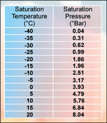
Table 1
Low temperature applications
A study of the pressure-temperature relationship of HCFC22 in Fig 3 shows how the rate of change of pressure diminishes in relation to temperature as the temperature is reduced. Table 1 shown below for HCFC22 illustrates this. Clearly, a greater amount of superheat is required at low temperatures to bring about a change in bulb pressure than is required at high evaporating temperatures. If the evaporating temperature were 5°C, an increase in superheat temperature of 5K will result in a pressure increase of 0.97bar (5.76 - 4.79). However, if the evaporating temperature were 40°C, an increase in superheat temperature of 5K will result in a pressure increase of only 0.27bar (0.31 - 0.04). This is a common characteristic of many refrigerants.
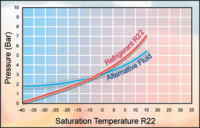
Figure 3: Pressure/temperature diagram for R22
Cross-charged expansion valves
Clearly, in low temperature applications, too much superheat is required to operate the valve resulting in a loss of valuable evaporator surface area and capacity. In order to avoid this situation, a cross-charged expansion valve bulb can be fitted in which another fluid is used instead of the system refrigerant type. This is normally a fluid with a much lower saturation temperature than the refrigerant used in the system to ensure adequate pressure change with temperature at the desired operating conditions. The term cross-charged arises from the fact that the pressure-temperature curve of the system refrigerant is 'crossed' by the pressure-temperature curve of the fluid in the bulb as illustrated in Fig 3.
Capacity range
There are limits to level of modulation to refrigerant flow that an expansion valve can satisfactorily control. In many systems there is a single, fixed-speed compressor and the expansion valve ensures that the correct refrigerant mass flow rate is delivered to the evaporator to meet the instantaneous and constantly varying thermal load. If the thermal load in an application is likely to fall to low levels, good practice demands the consideration of a split evaporator coil with an expansion valve for each circuit. Care must therefore be exercised in selecting the correct valve for the operating range of the application.
NEXT MONTH: Part 12 - Automatic and electronic expansion valves
With thanks to Mike Creamer of Business Edge who revisits his Masterclass series of articles, updating and adding to the information which proved so useful to readers when the series was first published over ten years ago. In this reincarnation, the series will cover both air conditioning and refrigeration and serve as an on-going source of technical reference for experienced personnel as well as providing a solid educational grounding for newcomers to our industry.