VRF (variable refrigerant flow) and VRV (variable refrigerant volume) technology is the same. VRV is the name trade-marked by Daikin for its systems. All other manufacturers use the the term VRF. Mitsubishi Heavy Industries offers a range of energy efficient systems. Over recent years there have been several technological changes within the design of the systems to ensure that the customer receives the most energy efficient solution to their requirements.
The major change within the area of comfort cooling systems has been change of refrigerants. Until recently most of these types of air conditioning system used R22 but, as we are aware, this is no longer an option. Many of the manufacturers have subsequently introduced new product ranges utilising HFCs.

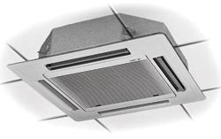
A VRF cassette
These refrigerants were developed as non-ozone depleting refrigerants and have been successfully used in a range of systems for many years. Manufacturers of air conditioning systems have tended to use R407C or alternatively R410A.
R410A
R410A is a zero ODP (ozone depleting potential) high efficiency refrigerant. It is a pseudoazeotropic refrigerant, which means, although it is a blend of R32 and R125 and therefore must be charged in its liquid phase, it behaves in the air conditioning system as though it were a single substance, with virtually no glide. R410A has much better heat transfer properties than many other common refrigerants. R410A also has much higher density, which creates the possibility of smaller tubing diameters in the heat exchangers and interconnecting pipework, along with a lower refrigerant charge.
R410A Installation
It is imperative that interconnecting pipework is installed by a competent engineer, certified under the F-Gas Regulations. R410A has a higher operating pressure (1.6 times that of R407C) therefore great care must be taken whilst undertaking the required strength and pressure leak tests of the equipment in accordance with BSEN 378. Pipe installation and connections must be made correctly, using the proper materials and tools. If it is necessary to braze pipework then a small positive flow of oxygen free nitrogen should be introduced within the system, this will ensure that no contamination occurs within the system.
Coefficient of performance
This is the terminology for measuring the useful heat output from a system, compared to the energy input. COPs in excess of 3.6 have been achieved on many of the systems, which means for every 1kW of electrical energy consumed, the system will deliver 3.6kW of heat into the conditioned space.
EEV electronic expansion valves
Every cooling/heating system has a compressor and an expansion device. Traditionally, expansion devices often consisted of a capillary tube with fixed parameters. The majority of manufacturers have now employed the same technology as used in the advanced VRF systems by using EEV.
This allows the optimum refrigerant flow and expansion pressure drop for all varying conditions at which the system is required to work. The result is higher performance and lower energy consumption.
Inverter technology
In order to achieve maximum efficiency, a new brushless DC motor compressor has been equipped with a neodymium magnetic rotor fitted to a range of outdoor units. This results in minimal start currents so it is not always necessary to upgrade power supplies for these systems. The combination of these inverter compressors, and the electronic expansion valves allow the refrigerant pressures and volumetric flow to be constantly monitored and adjusted. This provides a very stable and comfortable temperature condition, as well as savings in energy costs.

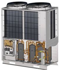
A Mitsubishi Heavy Industries KX4
condensing unit
Wired controllers
Correct and accurate control of the environment is achieved by the client via either wired controllers or by an optional wireless controller. The wired controller provides comprehensive control functions across a range of systems. The 24-hour programmable timer has four set times per day, two-on, two-off. The remote control option typically has a 24-hour clock (12 hours am and pm), and it is therefore possible to preset the required temperature during the operational periods.
A room temperature sensor is fitted within the wired controller, which can be used as an alternative sensor to the sensor in the return air.
This is sometimes useful for ducted units and for group temperature control.
The set temperature can also be limited to avoid excessive cooling or heating being operated by the user. The upper and lower limits can be
preset, to ensure stable temperature conditions, and to reduce wasteful energy consumption.
The wired controller has the function of cumulative hours run, as well as storing operation data when fault codes are registered. This helps
with fault diagnosis and rectification, as well as for planned maintenance.
A further control option within the wired controller is the night operation 'silent mode'. The outdoor unit can operated at reduced fan speed at
night to reduce the noise level. This function can be selected at the remote control, or can be programmed using the timer.
VRF multi-split systems
Over the last few years there has been a programme for all Japanese manufacturers to improve the efficiency and performance of both split air conditioning systems and variable refrigerant flow systems. This has been driven by rising electricity prices, and the near overload of the electricity supply grid in Japan.

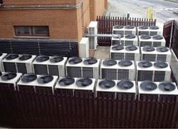
A large array of VRF condensing units
In 2003, most Japanese manufacturers were progressing with the development of variable refrigerant flow systems with higher performance ratios, based in R407C. Then one manufacturer launched its new range of variable refrigerant flow based on R410A. There was an aura of panic, as manufacturers quickly changed their development programmes and moved almost entirely to R410A systems.
Enhanced performance
The enthalpic properties of R410A have already been well documented. Its inherent higher performance characteristics have now been combined with inner-grooved tubing and multi-slit fins, as well as advances in the design of compressors, electronic expansion devices, refrigerant distributors, and refrigerant monitoring software.
Much larger heat exchanger face areas are now being used, with multiple leading edges to enhance heat transfer. This has allowed new fan design, and lower pressure drops and sound levels.
Small diameter piping
R410A is high performance refrigerant, which operates at higher pressure, compared to traditional systems. This allows the interconnecting refrigerant piping to be small diameter; for example the pipe terminations at the outdoor unit are 3/8in and 5/8in.
Communicating cabling
Each unit is connected by a two-core cable, which is non-polar, meaning that it does not matter if the connection terminals are switched between one unit and the next. All indoor units are addressed and connected by the communications cable to the outdoor unit.
Fuzzy logic control
The compressor is fully inverter driven, allowing its speed to be varied depending on the combined cooling or heating demand from each indoor unit.
The system will operate all on cooling, or all on heating. It is not possible to have individual operating in cooling and heating simultaneously.
Each indoor unit is fitted with an electronic expansion valve, which monitors the flow of liquid refrigerant or hot gas, depending on the temperature differential between the set condition and the return air. Information from the valve openings and indoor unit sensors is processed and communicated to the outdoor unit processor, which delivers the optimum amount of refrigerant, taking into account the ambient conditions.
Larger systems
While the traditional capacity range for variable refrigerant flow systems applied to commercial buildings is 22kW to 54kW cooling, the MHI KX4 range of outdoor units has been extended to 136kW, using outdoor units in combination.
All outdoor units are fitted with inverter compressors which provides for a wide range of cooling and heating capacities at part load, ensuring the efficiency and performance are maintained at the maximum possible level, and stable temperature conditions can be achieved in the conditioned space. It also eliminates high start currents associated with fixed speed compressors.
New outdoor units
These new units have a compact and slim profile design, with the enclosed compressor compartment separated from the airflow. This helps to reduce noise break out and ensures minimum sound levels. The heat exchanger surface has been increased by approximately 60% allowing reduced air velocity, improved heat transfer, less fan power and lower sound levels.
The DC fan motors are varied in speed, depending on the refrigerant condition, and the amount of energy transfer being demanded by the central processor.
Daikin VRV systems
The first ever Daikin VRV system installed in Japan in 1982 marked the beginning of a new era in the air conditioning industry. Until this point packaged air conditioning and chilled water systems were the usual solutions to a building's cooling requirement. However, with increasing restrictions on available installation space for outdoor condensing units and the revenue lost through installing in a plant room, which could otherwise be lettable space, another solution was required.
The first VRV systems were very similar to a typical modern-day multi-split or double-twin system with four indoor units connected to a single outdoor unit. This generally reduced the amount of space required for the outdoor units and with greater allowable pipe runs increased the installation flexibility. As building techniques improved and buildings themselves were being built taller and closer together the positioning of the external walls became more and more crucial.
Another area for concern was rising energy consumption and the associated costs. The Following table shows a breakdown of energy consumed in a typical office building;
Air Conditioning 47.2%
(Compressor 20%)
(Heat Transfer 27.2%)
Other utilities 20.5%
Lighting 32.3%
Almost half of the energy consumed is by the air conditioning. Breaking this down even further identifies the two main areas of consumption as the heat transfer process and the compressor.
These were the two areas focused on in the development of VRV.
Heat transfer
There are various heat transfer media that can be used to transport heat from one part of a building to another. Traditional methods include water, air and refrigerant. Using water as the heat transfer medium means that this water must firstly be cooled by a refrigerant cycle before being pumped around the building to cool the desired areas, ultimately meaning that there are two heat transfers which significantly reduce the system's efficiency.
Similarly, by cooling air centrally and then transporting it around the building, losses are incurred and again there is a secondary heat exchange between the cool air and the air in the space to be conditioned.
On top of this, to transport water or air around a building, large pipes or ducts are required which take up valuable space in the building that could be used for other services or provide more space.
Using refrigerant as the heat transfer medium means there is only one primary transfer of heat between the refrigerant and the air in the space to be conditioned and as the compressor is also the pump that moves the refrigerant around the building, there is no need for auxiliary equipment.
Refrigerants cool or heat using the latent heat absorbed or rejected through a change of state (ie, evaporation or condensation), which works out to be almost 10 times more transferrable heat than is possible in water and more than 20 times that possible in air. It is for these reasons that most manufacturers went down the route of direct expansion multi systems (VRV).
The compressor
The early system inverter compressor technology pioneered by Daikin in the late 1980s provided 14 steps of capacity control and used electronic expansion valves to ensure precise temperature control.
Inverter driven compressors increased system performance by 30% to 40% compared with previous systems using an on/off type compressor and the soft start means there are no current surges on start up.
The most recent scroll compressors incorporate a reluctance brushless DC motor which is significantly more efficient than conventional AC inverter motors and is very reliable as there are no brushes which would need replacing.
The motor uses digital commutating technology, which basically adopts an arrangement of superior strength magnets, which generate a reluctance torque as the current supply to the compressor alternates.
The torque generated by the magnets aids the rotation of the motor and thus reduces the electrical input required to turn the motor.
Adoption of the high-pressure shell has given greater control over the oil temperature improving the long-term integrity of the oil and the reliability of the system as a whole.
Reliability
As systems have grown larger, pipe runs have been extended and the maximum number of indoor units on a single circuit increased, reliability of the system has become evermore important.
Manufacturers' systems incorporate a number of reliability features intended to reduce/eliminate down time and aid the smooth running of the system.
Duty cycling of the compressors is a concept, which involves changing the order of compressor start-ups each time the system is switched on.
Traditionally, the same inverter (or master) compressor would start up each time thus meaning this compressor had the longest running hours and potentially the shorter operational life.
With duty cycling the start up sequence is cycled between condenser modules, which equalises all compressor running hours thus extending overall compressor life.
Keeping a sufficient amount of oil in each compressor is of utmost importance to the smooth running and life of the compressor. VRV systems can have two oil balancing functions that ensure the optimum amount of oil is present in all compressors. On a localised scale, the clever arrangement of compressors and their operating sequence, oil separators and interconnecting pipework ensures oil is present at the suction side to the compressors.
If more than one condenser is used in a single refrigerant piping system then oil is monitored and distributed between the condensing units to ensure equal levels are present. Oil equalisation is carried out every six minutes.
On top of this, an oil return operation, which flushes the indoor units to return any residual oil, is carried out at regular intervals.
Similarly, when more than one condensing unit is linked to a single system, the refrigerant stabilisation function monitors refrigerant levels in each of the condensing unit's receivers and balances the levels out between the other condensers using solenoid valves on the high and low pressure sides.
In the unlikely event of a compressor failing, two back up functions are in place. Firstly, in the case of just one condensing unit, the faulty compressor is isolated and the other(s) will continue to operate giving 50%-60% capacity. In the case of larger systems using multiple condensers, the advanced back-up systems ensure continued operation up to 80% of original capacity.
With thanks to Mike Creamer of Business Edge who revisits his Masterclass series of articles, updating and adding to the information which proved so useful to readers when the series was first published over ten years ago. In this reincarnation, the series will cover both air conditioning and refrigeration and serve as an on-going source of technical reference for experienced personnel as well as providing a solid educational grounding for newcomers to our industry.