1 March 2008
folder [featCategs]
Refrigerants: Designing to minimise leakage
[firstParagraph]
David Bostock of Grenco Refrigeration discusses the nature of refrigerant leaks, what they are, what causes them and what can be done through good design and engineering practices to reduce or eliminate the risk of measurable leaks occurring
.
THE worldwide focus on the effects of climate change and the measures being taken to combat it (such as the Montreal and Kyoto Protocols) have highlighted the need to improve the total emissions of refrigeration equipment.
Emissions are the total CO2 discharge of a plant including the energy used to power it (and the resulting CO2 emitted from the power station) and also the equivalent CO2 emitted in the form of refrigerant fluid escaping into the atmosphere. ODS, GWP, TEWI, LCCP and F-Gas have all become familiar acronyms for the tools, measures and regulations that we now apply to the impact of refrigeration systems on climate change.
The data for leakage rates varies widely, and of course depends on the source, scope (national, EU or worldwide) and the definitions used. Air conditioning can be any combination of domestic, commercial to industrial size. Supermarkets are sometimes included in commercial, and in some sources not.
Some data sources include catastrophic total system refrigerant charge losses and others exclude these to deal with only normal operational refrigerant leaks. From examining Tables 1 and 2 however, it becomes clear that there are opportunities in the larger capacity sectors for significant reductions in leakage rates.
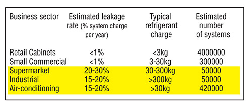
Table 1: Comparison of direct and indirect emissions, in EU ACR market sectors
Is zero leakage possible?
A leak is defined as: a hole or porosity in an enclosure capable of passing a fluid from the higher pressure side to the lower pressure side. A leak may be the tail-end of a weld fracture, a speck of dirt on a gasket or a microgroove between fittings. All sealed systems leak. The leak could be at 1kg/s or 1g/million years.
Every pressure system has leaks because flaws exist at every joint fitting, seam or weld. These flaws may be too small to detect even with the best leak detection instruments. But given time, vibration, temperature and environmental stress, these flaws become larger, detectable leaks.
What do we mean by the term Risk of Refrigerant Leakage? From our Health and Safety obligations we are all familiar with the ideas of likelihood and severity in terms of risk management. There is always a risk of leakage, and there always will be leakage from refrigeration systems, it is just a question of likelihood and severity - how likely is a measurable leak to occur, and how large will it be if it happens (for example - discharge from a safety relief valve, or a ruptured pipe). In answer to the question - Is zero leakage possible? - technically the correct answer is 'no'.
We do however live in a practical world, and have to use practical standards and measures by which we can judge ourselves, and so we need to make some definitions about leakage, practical measurement of leaks and what aspects of design can be improved to address the rate of leakage from 'sealed' systems.
Table 2: Comparison of direct and indirect emissions, in EU ACR market sectors
What is an acceptable leakage rate?
So if theoretically no system can be completely leak tight - what is the practical definition of leak tight?
A sealed system which operates for its useful life (say 20 years) without ever needing additional refrigerant to be added, in order to keep it running within normal operating parameters is considered to be leak tight. That means that it has not leaked enough refrigerant to affect system performance (typically less than 10% of original charge, although some studies show that this may be as high as 20% before performance loss can be detected. Below this 10% lifetime benchmark the system leaks are not practically measurable - and it is deemed a leak tight system.
Leaky gases
It is often heard that the newer HFCs are leakier than the more traditional HCFCs because they have smaller molecules. Is there any truth in this?
Assuming that we can discount major leaks of liquid refrigerant (the risk of these will be dealt with later); we are trying to minimise the operational gas leaks in a system. We therefore need to understand a little about how gas leaks operate.
There are four predominant gas flow modes through leaks:
Turbulent 10-2 std.cc/s
Laminar 10-1 to 10-7 std.cc/s
Transition 10-4 to 10-7
std.cc/s
Molecular 10-6 std.cc/s
1.0 standard cc/s = one cubic centimetre of gas flow per second at 1.0 bar and 20.0ºC.
We can see from these leak rates that the area of greatest concern (largest leak rate) is the laminar and turbulent gas flow modes. The dominant gas characteristic in these flow modes is viscosity, and for a given leak or flaw, then the leakage rate is inversely proportional to the gas viscosity. Hence, the lower the viscosity, the greater the gas leak flow rate.
Where the leak or flaw is very small (microscopic), then the flow mode is molecular, and then the dominant gas characteristic is molecular weight (actually molar volume) - the smaller the gas molecule, then the greater the flow rate (all other parameters being equal). Table 3 shows viscosity and molecular weights for common refrigerants, and as a matter of interest the bottom six are - or were - considered common tracer gases for leak testing of leak-critical pressure systems and equipment. Refrigerant mixes are not shown, but rather their constituent fluids, as we are particularly interested in the loss of the lighter gases from a mix.
Therefore, if we focus on our measurable leaks (laminar/turbulent flow modes), then lower gas viscosity makes one refrigerant leakier than another. To put things in perspective (and to better understand what a standard cc/s looks like) Table 4 shows leakage rates (time) for a cc and 1kg.
So, by our earlier definition of leaktight (maximum 10% refrigerant charge loss over the 20 year life of a system), we are interested in leaks down to the 10-3 to 10-4 scale for our larger capacity systems (assuming a minimum10kg refrigerant charge).
The leakage rate
The standard definition of leak rate is: a leak rate of 1.0mbar l/s exists in a closed vessel having a volume of 1.0 litre when the pressure decreases by 1.0 mbar within 1.0 second.
The basic formula for determining the leak rate of a pressure dependant leak (and all leaks are pressure dependant in terms of the rate of leakage) is:
QL = V∆p / ∆t
QL = Leak rate mbar //s
V = Volume flow rate of gas l/s
∆p = Pressure difference across the flaw (hole)
∆t = Time interval
Clearly, if a system operates with a lower pressure differential from the pressure containing element to atmosphere; then the rate of leak (because there is always some leakage) is reduced. If the element of the pressure system is operating below atmospheric pressure, then of course any leak flows from atmosphere to inside the pressure system. Air is thus introduced into the system.
Although this is not a refrigerant loss situation, the introduction of non-condensable gases to the system has a different effect; and the resultant increase in condensing pressure, increases the power consumption of the plant, and therefore increases the total emissions of the plant.
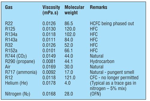
Table 3: Gas viscosity and molecular weight for various refrigerants +1.0 bar, superheated + 25 degrees celsius
The growth or development of leaks
There are different types of leaks, or rather there are different root causes for leaks to develop to the point of becoming measurable and hence of concern.
Standing leaks (SL) - are leaks that can be detected while the unit is at rest (off) and fully equalised. This includes evaporator coils warmed up by defrost. Standing leaks are the most common type of leak.
Pressure dependant leaks (PDL) are leaks that can only be detected as the pressure is built. Nitrogen or helium is used to pressurise the system, and then a leak test is carried out. Various methods can be used - bubble formation, helium sniffer, acoustic.
Temperature dependant leaks (TDL) are leaks associated with the heat of expansion. TDL usually occurs when the operating temperatures of systems are subject to a high temperature difference, and repetitive expansion and contraction, such as during defrost.
Vibration dependant leaks (VDL) occur only during unit operation. The mechanical strain of motion, rotation, refrigerant flow or valve actuation, are all associated with VDL. Vibration or pipe movement as a result of liquid hammer would come under this category.
Combination dependant leaks (CDL) are flaws that require two or more conditions in order to induce leakage. For example, temperature vibration and pressure cause the discharge manifold on a semi-hermetic compressor to expand and seep gas.
Cumulative micro-leaks (CML) are all the individual leaks that are too small to detect with standard tools. The total loss over many years of operation slightly reduces the initial gas charge. In practice, a system having many fittings, welds, seams or gasket flanges; will have a higher total CML loss.
A system designer must consider all these types of potential leak when determining the best practice for their particular application, and then try to minimise the impact of each in the overall leakage rate from their system.
Design opportunities to minimise leakage impact on total emissions
a) Use a non-HFC refrigerant
b) Reduction of refrigerant charge per unit of cooling capacity
c) Recovery of refrigerant during service and end-of-life
d) Reduced refrigeration capacity demand
e) Leaktight systems
a) Non-HFC refrigerant
Reducing leakage in this context refers to F-Gases, whilst measurable leaks of any refrigerant are to be minimised (and for flammable refrigerants will be dangerous), in order to reduce the impact on the climate, leakage of a natural refrigerant would be less harmful.
Many 'new' non-HFC refrigerants are being seriously studied and tested in practical situations, and are in effective use in some cases for a number of years now. Carbon dioxide (actually a very old refrigerant) is becoming more commonplace with very attractive efficiencies.
This may also include the use of indirect systems in place of direct, for example in large supermarkets, although the potential loss of efficiency must be offset against the gain (reduction) in direct HFC losses.
b) Reduction of refrigerant charge
It is difficult to make blanket statements that give all-encompassing solutions to the problem of refrigerant charge reduction. Energy efficiency factors must also be considered in the total emissions of a plant. Each application and situation must be considered on its own merits; but typical examples of charge reduction and limited charge technology are:
· Distributed supermarket systems where water cooled condensing units are used local to the evaporator, in order to reduce refrigerant containing pipe run lengths.
· The use of plate or plate and shell heat exchangers in place of shell and tube, so that heat exchanger internal volumes are minimised.
· Replace direct expansion (DX) systems with primary/secondary cooling systems. The secondary fluid can be a single phase fluid such as glycol, or a volatile secondary such as CO2. For lower temperature requirements, cascade systems using CO2 on the low side can also be considered.
· Centralisation of many small systems with a single central plant incorporating both common standby capacity and heat load diversity, thus reducing total equivalent system volumes and charges.
· Eliminate 'dead' refrigerant storage space in vessels (such as HP receivers).
· Reduction of heat load and therefore reduction of plant capacity and size/volume required.
c) Recovery of refrigerant during service life and dismantling/disposal
Although we are not examining service aspects, from a design standpoint it is very important that the designer of a refrigeration system considers the service and maintainability of a plant at the design stage. If refrigerant cannot be recovered from sections of the plant that need to be broken into for service and maintenance (maintenance is required to ensure optimum performance and efficiency) then it is inevitable that refrigerant loss will occur. It must also be possible to inspect (and leak test) all joints in a system, and so the designer must ensure that this is possible.
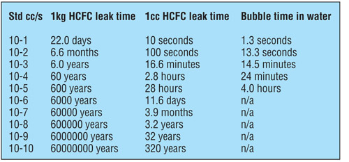
Table 4: Time measurement of standard leak rates
d) Reduced refrigerant capacity demand
A reduction of installed capacities will also have the effect of reducing system size, hence refrigerant charge and hence leak potential (by reducing the number and size of joints used). Although this seems a strange way to reduce the leakage rate, remember we are interested in reducing leakage in order to minimise the total emissions from a refrigeration plant. Total system refrigerant charge, joint quantity and power consumption all have an effect on total emissions. Some typical examples of methods for reducing heat loads and plant capacity are:
· Thermal Storage systems and technology for peak heat load reduction, including principles such thermal storage by 'night-time' running.
· Select equipment based on normal running parameters and not '1% design conditions'. Consider the running of standby plant or capacity to cope with peak load periods.
· Improved door management systems and procedures for temperature controlled spaces. Consider options such as closed display cabinets instead of open, and automated pallet conveyor loading systems and air locks for pallet transfers to and from cold and chill stores.
· Use dehumidification technology to improve the heat exchange efficiencies at sub-zero air coolers, and to reduce defrost heat loads.
· Employ free-cooling systems to make the maximum use of ambient air dry and wet bulb temperatures, to minimise the requirement for mechanical cooling.
· Reduce heat loads where possible by examining process flows and work patterns.
· Cool products at the most appropriate temperatures, to minimise the temperature differences between air/product and refrigerant, and to allow the refrigeration system to operate at the highest possible evaporating pressures.
Leaktight systems
Many things can, and already have been done to reduce, by small measures in each specific circumstance, the potential for measurable leaks from a system. We have looked at the different types of leak source, and each needs to be considered in any system design that is to be optimised for minimum refrigerant leakage.
Static Leaks - brazed, soldered, welded joints, mechanical joints, unions, flanges, gaskets, schraeder valves, purge points, service valves, shaft seals, spindles, instrumentation, and pressure relief valve outlets are all sources of leak - it is just a question of how much.
A study on supermarket refrigeration systems carried out in Germany showed that: 96% of the total refrigerant loss was through field assembled joints; 15% (by number) were responsible for 85% (by weight) of the refrigerant loss; 22% of all measurable leaks were from flared joints, and these were responsible for 50% of the refrigerant losses.
In Fig 1, we can see that total losses account for a very large proportion of the total refrigerant losses. Total losses are catastrophic failures and typical examples of such failures are:
· Fork trucks hitting piping and equipment.
· Low temperature water systems (+0.5ºC to +2ºC) freezing on the water side, causing heat exchanger ruptures.
· Thermal expansion and contraction of piping that is incorrectly bracketed, causing stress cracking and failures at joints.
· Vibration induced stress cracking of piping at compressor connection points, and at points where liquid hammer occurs.
· Incorrectly set safety devices allowing systems to operate at conditions too close to safety relief valve settings, causing gas 'venting' to atmosphere.
Clearly measures have already been taken to address some of these issues, and the use of flared joints is already restricted under the guidelines of EN378:2000. The poor design of piping and bracketing is still however a major source of total system refrigerant charge losses.
Piping needs to be installed in such a way that all the joints can be easily accessed to allow (properly trained and qualified) installation engineers to make good leak-tight joints; and to allow future inspection of these joints. Bracketing needs to be designed to accommodate thermal and vibration induced movement without causing undue stresses that lead to failure.
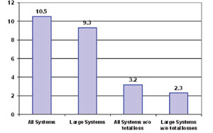
Fig 1: Annual leakages in % of system charge from supermarket systems (German leak tightness study)
Refrigeration equipment should be protected from accidental mechanical damage. Crash barriers, bollards, kerbs, and dedicated machinery rooms should all be used to ensure that the risk of damage to equipment and piping is minimised.
Another method of ensuring a better degree of leak tightness is to operate the plant at the minimum possible condensing pressure. The leak rate from the high side of the system will be reduced in a directly proportional measure as the pressure difference (condensing pressure to atmospheric pressure) is reduced. This is also of course the additional benefit of reduced power consumption, so that total emissions are reduced in both direct means (CO2 equivalent of the refrigerant leak) and indirect (CO2 emitted from the electrical power generation plant).
Ensuring that a newly installed or fabricated system is leaktight prior to initial refrigerant charging is obviously an important measure in reducing refrigerant leaks.
Helium leak testing is becoming the standard method for leak tightness testing for factory produced items, and allows more accurate and effective leak testing in a production environment. Helium testing is also becoming more popular for site installed piping, and is used as a tracer gas on oxygen free nitrogen - OFN (typically 5% helium). Helium leaks develop faster than pure OFN, and helium leaks can be detected to lower concentrations in air by electronic sensors, so that smaller leaks can be detected with helium than the more traditional bubble-test method with soapy water and pure OFN.
The integration of external components can also reduce the potential for leak from high risk areas such as external control switches. One good example is the incorporation of oil pressure switches on compressors. Eliminating the external tubing reduces the number of joints significantly.
One example of how two types of leak source can be minimised at the same time, is that of compressor discharge gas pulsation reduction. This not only minimises vibration dependant leaks, but also reduces pressure dependant leaks as well. In the case, the inclusion of a muffler design in the compressor cylinder head, damps down the spikes or pulsations of discharge gas from the compression cycle of a piston compressor. This reduces both vibration and pressure.
The STEK Regulations - What can we learn from the Netherlands?
Since 1994 the Netherlands has been operating an F-Gas style Regulatory system known as STEK. These regulations included design, service, maintenance, competence assessment and record-keeping requirements, and so was very wide ranging in terms of tackling the reduction of direct refrigerant emissions to atmosphere. The main items of STEK Regulations are:
Design criteria
· Pipes shall be joined by brazing or welding.
· Flared joints (of any size) shall not be used.
· Detailed requirements for safety relief valves and devices, usually venting to the low pressure side first and not directly to atmosphere.
· Systems with a refrigerant charge greater than 300kg shall be located in special machinery rooms.
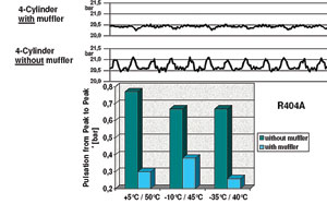
Fig 2: reduction of discharge gas pulsation in piston compressors
Service criteria
· Systems charged with greater than 3kg shall be inspected annually.
· Systems charged with greater than 1000kg shall be under constant supervision.
· Logbooks must be kept for all systems with a systems charge greater than 3kg.
· Refill or top-up is only permitted after the leak source is identified.
· After a leak is identified and repaired a follow-up visit shall be made to check the integrity of the repair.
· Qualifications for all service and installation engineers, in joining methods, and in-service leak testing.
· Documentation and recording of refrigerant usage for all systems with a systems charge greater than 3kg, to allow the effectiveness of the new measures to be monitored.
The STEK design requirements were very similar to the old BS4434, although there were specific regulations aimed at eliminating well-known sources of leaks. EN378:2000 went some way to closing the gaps, as some of the STEK requirements appeared in EN378:2000.
The design element difference is still in the area of leak detection equipment requirements and the point at which special machinery rooms are required. In terms of system designs however, there does appear to be a move towards more secondary cooling systems with both glycol single phase, and CO2 volatile secondary and cascade systems being installed in place of large direct HFC systems.
The main continuing benefit of the STEK regulations appears to be in the area of service, maintenance, competency and record keeping. Ensuring the competency of engineers in relation to joining methods and leak testing, proper record keeping and an effectively-policed system has seen annual leakage rates fall from the European average of 15% to 3-4%. There is some dispute over the effectiveness of the STEK approach, however from examining table 5, we can see that even with margin-for-error in how statistics are reported, there is a significant difference in annual leakage rates for countries with STEK style regulations in place (Sweden operates a very similar system to STEK).
Fig 5: Supermarket leak rate estimates
Conclusions
Design affects all aspects and types of risk events in relation to refrigerant leakage - the type of equipment, pressure envelope and containment system, material, joining method, seals, installation practice and quality, service friendliness and maintainability and even the ease with which the equipment and the fluid contents of the system can be dismantled and disposed of.
These are all elements that the designer must now consider when building even a simple refrigeration system. Many of these aspects are now covered by legislation and guidelines to good practice and so many of the minimum standards are now proscribed.
However, minimum standards still leave much room for improvement. The designer can adopt methods and approaches that decrease the likelihood of leaks and also reducing the severity of leaks when they occur.
Design is however a compromise between the very best possible practice and the cost of achieving the ideal. Whilst the contracting and service companies can make many improvements for little or no cost, the end users of refrigeration equipment must also face up to the certainty that more leaktight systems and reduced emissions will cost money, and they will have to pay more for the same net cooling effect - even if some of the increase can be offset by reduced energy and refrigerant gas bills.
This article was first presented as a paper at the Institute of Refrigeration Conference on November 29, 2007.