The primary purpose of shell and tube chillers is that of heat exchange, in vessel form, to cool a closed circuit, recirculating fluid flow, using refrigerant as the cooling medium. The thermodynamic process was shown in Part 3 of this series in the P-E diagram.
Shell and tube chillers are extremely efficient. Moreover, they are very compact, requiring only a small footprint and overall height. Maintenance, an important consideration in costs terms, is also fairly straightforward.
The concept of the shell and tube chiller is based on a large number of tubes formed into what is known as a tube bundle. Refrigerant flowing from the expansion device is passed into the tubes and progressively evaporates thereby producing a cooling effect through the latent heat of vaporisation.
The tube bundle is mounted within a steel shell and end caps are fitted to both ends of the shell. Water is passed over the tubes and gives up heat energy to the surface of the tubes at lower temperature. The water therefore leaves the shell and tube chiller several degrees lower than the entering water temperature. This is known as a dry type or direct expansion evaporator. The water enters the side of the shell at one end and leaves the side of the shell at the other. Shell and tube chillers are supplied with screwed or flanged water connections. A drain connection is normally incorporated to allow the water in the shell to be removed.
A typical arrangement of a dry type or direct expansion shell and tube chiller is shown in Fig 1. It is a more common arrangement for the refrigerant inlet and outlet to be at the same end as shown in the cutaway illustration in Fig 2. These are normally used with positive displacement compressors such as reciprocating, rotary or screw machines.
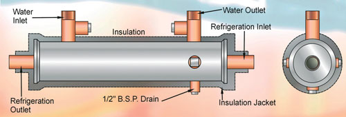
Figure 1: A typical arrangement of a dry type or direct expansion shell and tube chiller
Flooded evaporator
There is also a type of shell and tube chiller where the water runs through the tubes and the refrigerant flows over the outside of the tubes within a closed shell. This is known as a hooded arrangement or flooded type. However, this arrangement is not as common as the dry type of construction. Approximately 50% to 75% of the tubes are immersed in liquid refrigerant and the space above provides an allowance for the vapour generated through evaporation of the liquid below. This type is more often used with screw or centrifugal type compressors.
There is a variant of the hooded or flooded type known as the semi-flooded type where only the bottom row of tubes are immersed in the liquid refrigerant. A trough is often employed to ensure good distribution of liquid refrigerant along the full length of the evaporator as correct refrigerant distribution within the shell is important to ensure the tube bundle above is adequately wetted. The refrigerant liquid and vapour mixture is normally supplied to the bottom of the shell via a distributor that supplies the refrigerant evenly under the tubes.
The warmer liquid (water or brine) flowing through the tubes causes evaporation of the liquid portion of the refrigerant. The resulting vapour bubbles rise through the tube bundle and the liquid surrounding the tubes becomes frothy and also foams of oil is present in reasonable quantity.
The vapour leaving the surface of the liquid will contain liquid droplets in the form of a mist. This liquid mist must not be allowed to leave the evaporator shell or a loss of performance will result, coupled with possible accumulation of droplets into a sufficiently large quantity leading to partial compressor damage.
The provision of a large free volume in the shell above the tubes and liquid below results in a low velocity flow and allows the liquid mist and droplets to be retained whilst the remaining vapour is drawn out through the suction outlet. Mist eliminators or a coalescing filter can be used to separate the liquid droplets form the vapour if the upper free chamber is of insufficient volume.
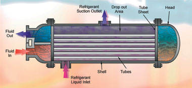
Figure 2:A dry type or direct shell and tube chiller with inlet and outlet at the same end
Recirculating medium Water is normally used as the recirculating medium for transferring heat energy from the building to the shell and tube chiller. There are many applications however that require both the entering and leaving water temperature to be subzero.
It may also be necessary to have the entering water temperature above zero and the leaving water below zero. In either case, the water must contain an additive that will prevent freezing and severe damage to the shell and tube chiller. These additives include the following:
• calcium chloride
• sodium chloride
• propylene glycol
• ethanol brine
• ethylene glycol
By varying the concentration of the additive in water, the freezing point can be varied to suit the application. A safety margin is also provided. Freeze point temperatures exceeding -50°C are attainable. These additives will be covered later in the series.
Baffle plates
The tube bundle may be several metres in length and the tubes require supporting to prevent sagging, which would otherwise impair correct distribution of water over the outer surface of the tubes. A series of baffle plates is therefore fitted along the length of the evaporator to support the tubes but these also serve another important role.
Were the water to be simply pumped in at one end of the tube bundle and allowed to run along the tube bundle without any disturbance or turbulence, a large proportion of the water might pass through the heat exchanger without making direct contact with the colder tubes. This would limit the heat exchange and thermal performance. Partial freezing of water might also occur under certain circumstances if the entire cooling power of the evaporator is dedicated to only part of the water flowing through the exchanger. This is especially likely to occur in any flow dead spot regions.
However, if the water were forced to change direction over a series of semi-circular baffle plates, the resulting turbulence will ensure thorough mixing of the water throughout the length of the heat exchanger thus leading to maximum performance and freeze protection.
The baffles also increase the velocity of the water throughout the exchanger, thereby increasing heat transfer coefficient. The velocity of the water flowing perpendicular to the tubes should be at least 0.6m/s (2ft/s) to continually clean the tubes and less than 3m/s (10ft/s to avoid tube erosion.
Baffle plate spacing
The number of baffles and baffle pate spacing is varied to produce different capacities from the same tube bundle assembly. An increase in the number of baffles increase the performance and capacity of the evaporator. The pressure drop experienced at the water pumps and subsequent pump input energy level increases however. ,b>Refrigerant distribution
The distribution of the liquid refrigerant in direct expansion, dry shell and tube evaporators must be absolutely uniform to all tubes in order to realise the required performance, efficiency and capacity. If some tubes receive more refrigerant than others, they will not be able to fully evaporate the liquid thereby leading to compressor flooding and possible failure. Superheat within these tubes will therefore be zero. Since the overall refrigerant flow is controlled by maintaining a pre-set superheat value at the expansion device, the remaining tubes will be forced to work at a higher than normal superheat level to evaporate the liquid passing through the other tubes thus forcing these tubes to operate at low efficiency and heat transfer. Even distribution of liquid refrigerant is achieved with a distributor or by ensuring that the volume of the inlet chamber is kept to a minimum to achieve constant flooding of the chamber and even flow through the entire tube bundle. Either method must maintain an even distribution of liquid refrigerant and flash gas vapour to all tubes.
Number of passes
The number of passes directly affects the performance of a direct expansion shell and tube evaporator. In a single pass evaporator, the refrigerant flows in at one end of the bundle and out at the other. This arrangement requires total evaporation of all liquid refrigerant and some superheat by the time the refrigerant leaves the tubes. This can require either a long tube bundle or some form of tube surface enhancement to increase the heat transfer and thereby a shorter tube bundle.
In a two-pass evaporator, the refrigerant normally travels in one direction through 50% of the tubes and returns to the same end of the bundle through the remaining 50% of tubes. This halves the length of the overall bundle that would otherwise be required but after the first pass, a large proportion (approximately 50%) of the refrigerant has been evaporated and even distribution of the remaining 50% is more difficult to attain, especially as this also has to turn through 180°. Whilst tube surface enhancement can therefore be avoided in this design, an ideal arrangement would be the combination of a two-pass evaporator and tube surface enhancement.
Multiple pass evaporators can be constructed to provide up to six passes in order to capitalise on the advantages described above. This is achieved by fitting different heads at either end of the shell in order to create the desired flow pattern back and forth through a standard tube bundle to suit the required capacity for the application. A similar technique is applied to water cooled condensers described earlier in the series.
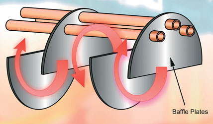
Figure 3: An increase in the number of baffles increase the performance and capacity of the evaporator
Tube surface enhancement
The performance of a two-pass evaporator, where the refrigerant travels in one direction through 50% of the tubes and returns to the same end of the bundle through the remaining 50% of tubes, suffers where, after the first pass, a large proportion (approximately 50%) of the refrigerant has been evaporated and even distribution of the remaining 50% is more difficult to attain, especially as the balance of refrigerant also has to turn 180° to return through the remaining tubes. Whilst this halves the length of the overall bundle that would otherwise be required, thereby leading to a more practical design for integration within a packaged water chiller, the partial loss of performance must be offset by increasing the length of the bundle accordingly.
Tube surface enhancement, for improved heat transfer, would offset the aforementioned disadvantages and the two-pass shell and tube evaporator incorporating tube enhancement is therefore an ideal arrangement.
The use of a tube-within-a-tube, and a spirally wound copper crimped fin insert promoted annular flow, and led to a great improvement in heat transfer unmatched by others at the time of its introduction. Since then, heat transfer development has continued throughout the air conditioning industry and a number of other enhancement techniques have been used. The most recent of these, the use of rifled microbore DX evaporator tubing, has allowed many manufacturers to offer compact shell and tube heat exchangers that can provide similar capacities to inner fin evaporators. The need to protect the environment against one of the causes of ozone depletion, ie CFCs, and to a much lesser extent HCFCs, has led to the devdevelopment of HFC refrigerants such as R407C and R134a. These refrigerants, although they have an ozone depletion potential (ODP) of zero, required package chiller manufacturers to replace the mineral oils normally used with CFCs and HCFCs with polyolester lubricants, in order to maintain satisfactory oil transport within their chiller systems.
It has been established, through extended factory testing, that the use of ester oils in evaporators having small bore rifled tubing can lead to a very significant reduction in capacity, as the grooved micro-rifling can become clogged with oil, partially transforming rifled tubes into smooth bore tubes. Evaporators that rely on performance enhancement via grooved tube may therefore be unable to translate the calculated performance specification into reality, resulting in a high evaporator approach, reduced efficiency and possible shutdown due to occasional tripping of safety devices.
The inner fin shell and tube evaporator does not suffer from loss of capacity when operating with high viscosity ester based lubricants. The comparatively coarse nature of the inner finning prevents oil logging, and a low approach is maintained. For this reason, many manufacturers have for some years used at least one viscosity grade higher than the mineral oil it replaces when selecting ester oil for a particular application. This provides adequate protection against thinning of the oil by the HFC refrigerant used, preventing accelerated compressor wear rates. The ability of 'Inner Fin' evaporators to maintain their performance when operated with HFC refrigerants and thicker oils offers an assurance that the specified performance will be attained.
Construction
The capacity range of inner fin’ direct expansion evaporators available can extend to 1200kW cooling capacity with the ability to specify up to four refrigerant circuits.
All evaporators feature single refrigerant and water passes in counter-flow configuration for optimal heat transfer and the greatest protection against freeze up. The smaller CH and DCH type evaporators feature copper tubes brazed into brass tube sheets.
The tube bundle is brazed into a steel shell, and steel end caps are then welded to the shell. Finally, the threaded or flanged water spigots are welded to the shell before pressure testing. Vessels may be supplied with the chilled water connection spigots arranged for vertical or horizontal connection.
Where potable water is to be chilled, shell and tube evaporators can be supplied with a standard copper tube bundle but with a stainless steel shell.
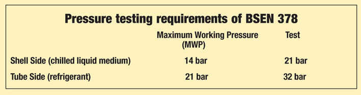
Where more aggressive fluids are to be chilled, the entire tube bundle, shell, baffle plates, tube plates and connections can be constructed from 316 grade stainless steel. The use of HFC refrigerants and ester oils places the manufacturer under a number of obligations. To ensure long term reliability of a chiller, it is vitally important that a proper pressure test and evacuation of the product is carried out to eliminate leaks. Typically, a DX evaporator would be pressure tested in accordance with BSEN 378. Thorough evacuation and dehydration between 200 and 250 microns provides additional reassurance that the vessel is totally leak free.
The use of a helium leak detection system may be employed if a vacuum shows signs of deteriorating over the 15 minute hold period. Finally, each vessel is charged with dry nitrogen at 0.5bar to prevent corrosion or moisture ingress during storage or transit.
As HFCs do have a reasonable global warming potential, and ester oils have a great affinity to absorb moisture, the importance placed on achieving a leak free and dry vessel cannot be overstated or this could lead to cross leaks, tube leaks and gasket problems. Next month: Shell and tube evaporators continued.
With thanks to Mike Creamer of Business Edge who revisits his Masterclass series of articles, updating and adding to the information which proved so useful to readers when the series was first published over ten years ago. In this reincarnation, the series will cover both air conditioning and refrigeration and serve as an on-going source of technical reference for experienced personnel as well as providing a solid educational grounding for newcomers to our industry.