
Direct spring loaded typeThe most popular type of relief valve is the direct spring loaded ‘pop’ type, where the piston generally contains a synthetic seat disc sealing against the valve seat by means of a spring and adjustable gland. At the relief valve setting, the force exerted by the spring is equal to the force exerted by the refrigerant pressure. As the pressure increases above the setting, the relief valve will begin to seep until there is enough flow to pop the piston open and provide full discharge. The pressure above the setting at which the piston is fully open depends on the relief valve design. Since the flow rate is measured at a pressure of 10% above the setting, it is necessary that the relief valve opens within this 10%.This type of relief valve operates on a fixed pressure differential from inlet to outlet. It is affected by back pressure so that it is not permissible to install a rupture member at the relief valve outlet. The ANSI/ASHRAE 15 Code does permit a rupture member to be installed between the pressure vessel and the relief valve inlet. The space between the rupture member and relief valve must be equipped with a pressure gauge or vent to indicate whether the rupture member has leaked or burst. If back pressure is allowed to build up in this space, the rupture member will not burst at its design pressure. The simple ‘pop’ type relief valve features low initial cost and high discharge capacity.Reseating after dischargingRelief valves are designed to reclose automatically at a predetermined pressure after they have discharged. The difference between the set pressure and the reclosing pressure is called the blowdown. The amount of blowdown will vary with the relief valve design and for most ‘pop’ type valves will be between 20% to 30% below the set pressure. Reseating should occur within 5% to 10% below the reclosing pressure. Failure to reseat tightly is generally due to an accumulation of dirt and foreign material on the relief valve seat disc which occurs while the relief valve is discharging. Since filters or screens are not permitted to be installed ahead of relief valves, for obvious safety reasons, this condition is likely to occur whenever dirt and foreign material are present in the system. For this reason it is almost impossible to predict, with any degree of certainty, the reliability of relief valves resealing after they have discharged in service.Diaphragm typeThe diaphragm (or bellows) type of relief valve is indirectly spring-loaded whereby the system pressure acts upon a diaphragm which lifts the piston from the relief valve seat. Since the external area of the diaphragm is exposed to atmospheric pressure, the relief valve setting is not appreciably affected by back pressure. This makes the diaphragm type particularly suitable for high side to low discharge in a refrigeration system. As the low side pressure increases, the relief valve setting will decrease slightly so that it will open at a pressure lower than the stamped pressure setting. The amount of decrease depends on the ratio of the seat area to the diaphragm area. For this same reason, the discharge capacity will actually increase up to a certain point with increasing back pressure. The disadvantages of the diaphragm relief valve are its high initial cost and relatively low capacity. It has the advantage of permitting the use of rupture member to be installed in series at the relief valve outlet to provide a dual seal. This can be done without affecting the safety of the installation and without the need for a pressure gauge or vent between the relief valve and rupture member.Use of three-way valvesThe dual relief valve installation consists of one three-way shut-off valve and two relief valves. The design of the three-way valve ensures that both relief valves cannot be shut off from the protected pressure vessel at the same time. This permits safe removal of either relief valve for repair or replacement, while the vessel is protected and under pressure.The use of a three-way valve with two relief devices, which meets the code requirements of vessels 10ft3 or more gross volume, is recommended for any installation containing a large quantity of expensive refrigerants.If two relief valves are used, the three-way valves should be tested so that full system pressure is applied to both relief valves. After checking for leaks, the three-way valve should be closed to one position so that only one relief valve is exposed to the variable system pressure.The three-way valve arrangement with two relief devices permits periodic checking and replacement when necessary, of either relief device while the system is operating. This can be accomplished without the need to blow the refrigerant charge.Installation considerations include providing a pressure vessel which will permit the relief valve to be set at least 25% above the maximum system pressure; selecting a relief valve having sufficient capacity for code requirements; selecting a relief valve suitable for the type of refrigerant used; using the proper size and length of discharge tube or pipe; not discharging the relief valve prior to installation or when pressure testing the system and for systems containing large quantities of refrigerant, using a three-way valve and two relief valves.Figure 1: The position of a high-pressure cutout switch Control, safety and protection devicesAs stated earlier, the low pressure cut-out switch can be used to regulate the desired temperature within the conditioned space. The differential setting of the low pressure cut-out will vary according to the level of accuracy required. A wide pressure differential will allow some variation in room, coldroom or display case temperature. This will also increase the length of the operating cycle of the compressor which effectively means the compressor will not run as often but would run for longer periods to in order to traverse the switch differential and restore the original setpoint.This is a more desirable situation in terms of compressor life due to the reduced number of starts. The increased run time of the compressor throughout each cycle will ensure good motor cooling in the case of hermetic and semi-hermetic machines and the overall cycle efficiency would be improved. A differential set to close limits however, would cause the reverse of the aforementioned but would provide closer space temperature control. The pressure difference between the cut-in and the cutout points varies with the refrigerant used.Protection against refrigerant leakageThe low pressure cutout switch is available in both auto and manual reset versions, although the auto reset version is most commonly applied. The reasons for auto versus manual reset are explained later in this article.The low pressure switch provides protection in the event of a refrigerant leak by tripping at a low pressure setting commensurate with the loss of all liquid refrigerant from the system. The remaining vapour falls in pressure and once the low pressure switch has tripped, preventing compressor operation, the system cannot restart until the problem has been resolved. This prevents the primary enemies, air and moisture, being drawn into the system.Nuisance trippingUnder cold ambient conditions, the low pressure switch will often operate shortly after the compressor starts thereby disabling the system’s ability to meet cooling demand. This is sometimes referred to as nuisance tripping.Nuisance tripping of the LP cutout is caused when the system attempts to start with a very cold condenser coil or cold condenser water in the case of a water-cooled system. When the compressor is not operating, the system high and low side pressures are normally equal and this is known as the standing pressure. All systems experience an immediate drop in low side pressure and an increase in high side pressure as the compressor starts and under normal circumstances where the condenser coil is located in warm ambient air the LP switch will not trip. However, when the condenser coil is cold it is easily able to condense the refrigerant vapour into saturated liquid due to increased efficiency through large temperature difference. The high side pressure of the system is therefore relatively low when compared to normal summer operation. Since the compressor is not required to generate a high discharge pressure, its ability to create a low suction pressure increases. In addition, the thermal load in the conditioned space may also be low and the evaporator fans will have just started to run. The amount of liquid refrigerant being evaporated is also reduced and is not sufficient to satisfy the flow-rate demands of the compressor. A very low, low-side pressure results and the low pressure cutout will then operate and stop the compressor.A solution to nuisance tripping is the inclusion of a time delay relay that is used to short out the contact of the low pressure switch for a limited period at each start up. The system is therefore allowed to run outside of the protection limit normally afforded by the low pressure switch until the load at the evaporator is established and the condenser coil is heated by hot discharge refrigerant/latent heat of condensation. After the compressor has run for a period of say two minutes, the contacts of the time delay relay are opened and the low pressure switch resumes protection. Microprocessor-based electronic control systems incorporate routines in respect of the low pressure cut-out trip message and can control the number of start attempts, the time between each attempt, a refusal to attempt restart beyond a given number of attempts, referral to ambient and condenser coil temperature, evaporator return air and coil temperature, etc.High-temperature alarmThe low pressure control could also be used to sense the suction pressure for alarm control on remote evaporation systems. An abnormally high suction pressure indicates excessive evaporator temperature and the low pressure alarm control contacts will close. Typically, this control would be used in conjunction with an automatic reset time delay device. The alarm control energises the time delay and if the suction pressure does not return to a normal level within the time delay setting, then the timer contacts close activating the alarm after the pre-set period has elapsed to avoid nuisance alarms.High pressure cut-out switchAs with the low pressure cutout, the high pressure cutout can also be used as a control and protective system component. When used as a protective device, the switch is set to operate when a given pressure is experienced on the high side of the system. This prevents the system operating in excess of the allowable pressure (previously known as MWP – maximum working pressure).CausesThe causes of excessive system pressure beyond the safe allowable pressure include: excess refrigerant charge; faulty or incorrectly set components such as valves, fan speed controllers; system high side restriction or blockage (TEV, drier, etc); condenser fan or motor failure, motor overload trip, control defect, etc; condenser coil blockage, short cycling of condenser airflow, deterioration of coil fins; and excessive ambient temperature coupled with high space thermal loading beyond system design limits.
Direct spring loaded type
The most popular type of relief valve is the direct spring loaded ‘pop’ type, where the piston generally contains a synthetic seat disc sealing against the valve seat by means of a spring and adjustable gland. At the relief valve setting, the force exerted by the spring is equal to the force exerted by the refrigerant pressure. As the pressure increases above the setting, the relief valve will begin to seep until there is enough flow to pop the piston open and provide full discharge. The pressure above the setting at which the piston is fully open depends on the relief valve design. Since the flow rate is measured at a pressure of 10% above the setting, it is necessary that the relief valve opens within this 10%.
This type of relief valve operates on a fixed pressure differential from inlet to outlet. It is affected by back pressure so that it is not permissible to install a rupture member at the relief valve outlet. The ANSI/ASHRAE 15 Code does permit a rupture member to be installed between the pressure vessel and the relief valve inlet. The space between the rupture member and relief valve must be equipped with a pressure gauge or vent to indicate whether the rupture member has leaked or burst. If back pressure is allowed to build up in this space, the rupture member will not burst at its design pressure. The simple ‘pop’ type relief valve features low initial cost and high discharge capacity.
Reseating after discharging
Relief valves are designed to reclose automatically at a predetermined pressure after they have discharged. The difference between the set pressure and the reclosing pressure is called the blowdown. The amount of blowdown will vary with the relief valve design and for most ‘pop’ type valves will be between 20% to 30% below the set pressure. Reseating should occur within 5% to 10% below the reclosing pressure. Failure to reseat tightly is generally due to an accumulation of dirt and foreign material on the relief valve seat disc which occurs while the relief valve is discharging. Since filters or screens are not permitted to be installed ahead of relief valves, for obvious safety reasons, this condition is likely to occur whenever dirt and foreign material are present in the system. For this reason it is almost impossible to predict, with any degree of certainty, the reliability of relief valves resealing after they have discharged in service.
Diaphragm type
The diaphragm (or bellows) type of relief valve is indirectly spring-loaded whereby the system pressure acts upon a diaphragm which lifts the piston from the relief valve seat. Since the external area of the diaphragm is exposed to atmospheric pressure, the relief valve setting is not appreciably affected by back pressure. This makes the diaphragm type particularly suitable for high side to low discharge in a refrigeration system. As the low side pressure increases, the relief valve setting will decrease slightly so that it will open at a pressure lower than the stamped pressure setting. The amount of decrease depends on the ratio of the seat area to the diaphragm area. For this same reason, the discharge capacity will actually increase up to a certain point with increasing back pressure. The disadvantages of the diaphragm relief valve are its high initial cost and relatively low capacity. It has the advantage of permitting the use of rupture member to be installed in series at the relief valve outlet to provide a dual seal. This can be done without affecting the safety of the installation and without the need for a pressure gauge or vent between the relief valve and rupture member.
Use of three-way valves
The dual relief valve installation consists of one three-way shut-off valve and two relief valves. The design of the three-way valve ensures that both relief valves cannot be shut off from the protected pressure vessel at the same time. This permits safe removal of either relief valve for repair or replacement, while the vessel is protected and under pressure.
The use of a three-way valve with two relief devices, which meets the code requirements of vessels 10ft3 or more gross volume, is recommended for any installation containing a large quantity of expensive refrigerants.
If two relief valves are used, the three-way valves should be tested so that full system pressure is applied to both relief valves. After checking for leaks, the three-way valve should be closed to one position so that only one relief valve is exposed to the variable system pressure.
The three-way valve arrangement with two relief devices permits periodic checking and replacement when necessary, of either relief device while the system is operating. This can be accomplished without the need to blow the refrigerant charge.
Installation considerations include providing a pressure vessel which will permit the relief valve to be set at least 25% above the maximum system pressure; selecting a relief valve having sufficient capacity for code requirements; selecting a relief valve suitable for the type of refrigerant used; using the proper size and length of discharge tube or pipe; not discharging the relief valve prior to installation or when pressure testing the system and for systems containing large quantities of refrigerant, using a three-way valve and two relief valves.

Figure 1: The position of a high-pressure cutout switch
Control, safety and protection devices
As stated earlier, the low pressure cut-out switch can be used to regulate the desired temperature within the conditioned space. The differential setting of the low pressure cut-out will vary according to the level of accuracy required. A wide pressure differential will allow some variation in room, coldroom or display case temperature. This will also increase the length of the operating cycle of the compressor which effectively means the compressor will not run as often but would run for longer periods to in order to traverse the switch differential and restore the original setpoint.
This is a more desirable situation in terms of compressor life due to the reduced number of starts. The increased run time of the compressor throughout each cycle will ensure good motor cooling in the case of hermetic and semi-hermetic machines and the overall cycle efficiency would be improved. A differential set to close limits however, would cause the reverse of the aforementioned but would provide closer space temperature control. The pressure difference between the cut-in and the cutout points varies with the refrigerant used.
Protection against refrigerant leakage
The low pressure cutout switch is available in both auto and manual reset versions, although the auto reset version is most commonly applied. The reasons for auto versus manual reset are explained later in this article.
The low pressure switch provides protection in the event of a refrigerant leak by tripping at a low pressure setting commensurate with the loss of all liquid refrigerant from the system. The remaining vapour falls in pressure and once the low pressure switch has tripped, preventing compressor operation, the system cannot restart until the problem has been resolved. This prevents the primary enemies, air and moisture, being drawn into the system.
Nuisance tripping
Under cold ambient conditions, the low pressure switch will often operate shortly after the compressor starts thereby disabling the system’s ability to meet cooling demand. This is sometimes referred to as nuisance tripping.
Nuisance tripping of the LP cutout is caused when the system attempts to start with a very cold condenser coil or cold condenser water in the case of a water-cooled system. When the compressor is not operating, the system high and low side pressures are normally equal and this is known as the standing pressure. All systems experience an immediate drop in low side pressure and an increase in high side pressure as the compressor starts and under normal circumstances where the condenser coil is located in warm ambient air the LP switch will not trip. However, when the condenser coil is cold it is easily able to condense the refrigerant vapour into saturated liquid due to increased efficiency through large temperature difference. The high side pressure of the system is therefore relatively low when compared to normal summer operation. Since the compressor is not required to generate a high discharge pressure, its ability to create a low suction pressure increases. In addition, the thermal load in the conditioned space may also be low and the evaporator fans will have just started to run. The amount of liquid refrigerant being evaporated is also reduced and is not sufficient to satisfy the flow-rate demands of the compressor. A very low, low-side pressure results and the low pressure cutout will then operate and stop the compressor.
A solution to nuisance tripping is the inclusion of a time delay relay that is used to short out the contact of the low pressure switch for a limited period at each start up. The system is therefore allowed to run outside of the protection limit normally afforded by the low pressure switch until the load at the evaporator is established and the condenser coil is heated by hot discharge refrigerant/latent heat of condensation. After the compressor has run for a period of say two minutes, the contacts of the time delay relay are opened and the low pressure switch resumes protection. Microprocessor-based electronic control systems incorporate routines in respect of the low pressure cut-out trip message and can control the number of start attempts, the time between each attempt, a refusal to attempt restart beyond a given number of attempts, referral to ambient and condenser coil temperature, evaporator return air and coil temperature, etc.
High-temperature alarm
The low pressure control could also be used to sense the suction pressure for alarm control on remote evaporation systems. An abnormally high suction pressure indicates excessive evaporator temperature and the low pressure alarm control contacts will close. Typically, this control would be used in conjunction with an automatic reset time delay device. The alarm control energises the time delay and if the suction pressure does not return to a normal level within the time delay setting, then the timer contacts close activating the alarm after the pre-set period has elapsed to avoid nuisance alarms.
High pressure cut-out switch
As with the low pressure cutout, the high pressure cutout can also be used as a control and protective system component. When used as a protective device, the switch is set to operate when a given pressure is experienced on the high side of the system. This prevents the system operating in excess of the allowable pressure (previously known as MWP – maximum working pressure).
Causes
The causes of excessive system pressure beyond the safe allowable pressure include: excess refrigerant charge; faulty or incorrectly set components such as valves, fan speed controllers; system high side restriction or blockage (TEV, drier, etc); condenser fan or motor failure, motor overload trip, control defect, etc; condenser coil blockage, short cycling of condenser airflow, deterioration of coil fins; and excessive ambient temperature coupled with high space thermal loading beyond system design limits.
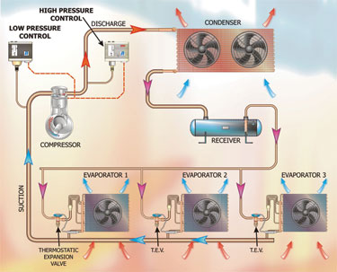
Figure 2:Separate high and low pressure control
Effects
The effects of excessive system pressure beyond the safe allowable pressure include: explosion – compressor body, heat exchangers or refrigerant lines; liquid refrigerant release due to rupture; compressor mechanism failure; compressor motor trip (over-current or over-temperature); reduced system efficiency and capacity; excess energy consumption + CO2 emissions. Clearly, some of the above are extremely hazardous and can cause death or severe injury. Fig 1 (shown on previous page) depicts the position of a high pressure cutout switch sensing compressor discharge pressure on the condenser side of the compressor being used as a high pressure protection limit control. The operating and differential ranges for high pressure cutouts operate up to 30bar (440psi) with a differential of 3.2 to 8bar (47 to 118psi).
Fig 2 shows separate high and low pressure cutouts fitted to a refrigeration circuit. In this case the LP cutout is being used for control whilst the HP cutout is being used for protection. A multiple evaporator system has been used in this illustration.
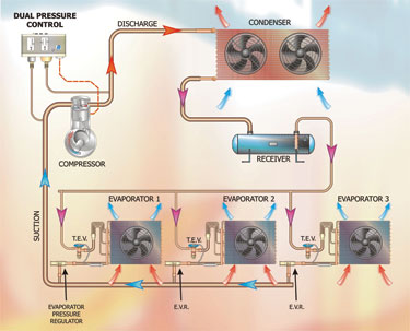
Figure 4: Dual pressure control
Low and high pressure switch – combined
It is sometimes desirable to have both the low and high pressure cutout switches located in one housing. This eliminates labour associated with mounting the device. Illustrations of this combined type of switch are shown in Fig 3. Whilst the two switches shown appear identical, there are some subtle differences including: ammonia and TUV options; option of assurance against rising and falling pressure; stainless steel bellows to suit high pressure systems/refrigerants; dual signal switch with independent high and low pressure operation; OR: SPDT switch (single pole-double throw); IP44 enclosure rating; various combinations of auto or manual reset on HP and LP functions.
Another use for this arrangement is in the form of a dual pressure control. In order that the system can be cycled with the LP control and in the event of excess high pressure due to say a blockage in the condenser, the HP control would shut down the system. This can be achieved using a dual pressure control (Fig 4) with exactly the same result.
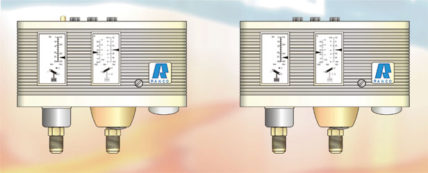
Figure 3: Dual pressure switches
Auto-reset and manual reset
Low pressure cutout – auto-reset It is normal for the low pressure cutout to be configured for auto reset. This allows the LP cut-out to automatically reset after a cold start has caused it to nuisance trip as described earlier. If there is a refrigerant leak and the low side pressure falls below the setpoint of the LP cutout, the compressor will be stopped and cannot restart until the system is repaired and recharged, thus bringing the standing and operating pressures up to a level in excess of the setpoint. The system compressor(s) cannot therefore start and draw in air and moisture. In the event of the application or system being critical for one reason or another, it may be that the designer will want to install a manual reset LP cutout. These have been applied to microprocessor-driven applications where additional protection has been added to that offered by the controller and software routines. High pressure cutout – manual reset Should the high pressure cutout operate, it must always be assumed that the system has attempted to exceeded the safe allowable pressure and that this situation might repeat itself if the system were allowed to attempt another start. It is for this reason that the HP cutout is normally always configured to trip and shut down the compressor(s) indefinitely. This forces the user or system owner to notice that refrigeration is no longer being provided and a refrigeration engineer is then summoned to investigate the problem. As you know, a “real refrigeration engineer” will diagnose that the high pressure cutout has been activated and will then determine the cause of the problem rather than simply resetting the switch!
There are applications for auto-reset high pressure cutouts. These have been used on special applications by our company, Advanced Refrigeration Technology Ltd. However, a common application of the auto-reset HP cutout is that of low ambient control.
NEXT MONTH: Part 20 – Control, safety and protection devices used in the vapour compression cycle continued
With thanks to Mike Creamer of Business Edge who revisits his Masterclass series of articles, updating and adding to the information which proved so useful to readers when the series was first published over ten years ago. In this reincarnation, the series will cover both air conditioning and refrigeration and serve as an on-going source of technical reference for experienced personnel as well as providing a solid educational grounding for newcomers to our industry.