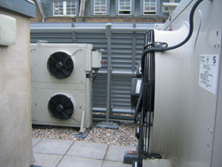
Windmilling effect
When the condenser fan(s) are switched off, wind blowing in the opposite direction to the condenser air flow will cause the fans to windmill in the wrong direction which may lead to nuisance overload trips on fan motor start up. Low noise units are the most susceptible to this problem.
Some manufacturers incorporate an anti-windmilling device on every fan, which is similar to a low friction ratchet to prevent the fan running backwards. Externally mounted water chillers with integral condensers and multiple fans are often fitted with anti-windmilling devices to prevent one or more fans not in use running backward due to reverse airflow currents created by other fans which are still in operation. Vertical coil units should be positioned such that the coil inlet face is not in direct sunlight. The surface temperature generated by solar radiation in the UK can easily exceed 50°C on dark surfaces and this can severely reduce the capacity of the condenser.
C. Condensing pressure control
Condensing pressure control is also known as head pressure control or low ambient control. There are only two ways to provide condensing pressure control on an air-cooled condenser:
(i) By varying the volume of the air passing through the coil (ii) By varying the amount of internal tube surface that the refrigerant gas can come into contact with.
It is possible, and sometimes necessary, to combine both of the above. Due to the way in which an air-cooled condenser works, it is difficult to find a convenient point in the coil block where the gas will only ever be condensing rather than de-superheating or where liquid is sub-cooling. This makes it practically impossible to use the condensing temperature as a signal reference to control the operation of the fans. The pressure within the coil however is constant whether the refrigerant is de-superheating, condensing or sub-cooling and is therefore the best reference to use as the control signal. However, this is more expensive.
When considering varying the air volume as a means of condensing pressure control, it should be born in mind that the relatively hot coil will induce air flow even with all fans stopped. The capacity this will provide is dependent on the coil detail and the temperature difference between the coil and air temperatures but is not affected by the design air volume.
It follows therefore that the capacity of a unit with a low design air volume will be proportionately greater with all fans stopped than for a unit using the same coil but with a high design air volume. As a guide, a high air volume, high noise level, unit might be capable of 10 to 15% of its design capacity with stationary fans while a low air volume, low noise level, unit using the same coil might be capable of in excess of 30% of its design capacity. Variation of the amount of air passing over the coil can be achieved in the following ways:
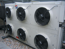
1. Changing the number of fans running (fan cycling) Individual fan wiring, starters and switching controlled by sensing the refrigerant pressure would be required. In the case of single-phase fan motors, starters may not be required if the motors are internally protected.
2. Varying the fan speed Single-phase fan motors can often be speed controlled using a simple pressure sensing controller varying the voltage at the motor. More than one motor can be controlled by a single controller within its current carrying capacity. The motors would require internal protection since over-current on a single motor could not be satisfactory detected by a controller running several fan motors. The speed of three phase motors can be controlled either by a triac-based controller or an inverter system. While the triac controller is cheaper it is less kind to the motors, can induce motor noise and does not provide motor protection. An inverter, particularly one which can vary both the voltage and the frequency, will not stress the motor, will provide motor protection, will not create motor noise and will also reduce the energy taken by the fan motor as the speed falls.
3. Combining the above It is possible to combine fan speed control with a fan cycling arrangement and it is only necessary to ensure that the switching differential and fan speed controller operating band are compatible to achieve an acceptable working arrangement.
D. Damper control
Usually used on condensers fitted with centrifugal fans, it is also used where insufficient fans makes fan cycling inappropriate and where fan speed control is either not available or not cost effective. The system is best employed on units mounted within buildings or where the damper system can be wholly contained within the condenser housing to avoid the dampers and/or linkages freezing in winter. Dampers can be motorised or controlled by actuators responding directly to the refrigerant pressure within the system. Variation of the amount of internal surface can again be achieved in several ways:
1. Liquid flooding Also known as liquid back up, this reduces the rate at which the liquid refrigerant can leave the condenser causing it to back up and cover a portion of the internal tube surface. A valve designed to maintain its upstream pressure (the back up or hold back valve) is installed in the liquid drain line to control the flow of liquid, while a pressure reducing valve is installed in a line connecting the discharge line and liquid receiver, which prevents the receiver pressure falling below a predetermined level. In small installations the valves are often combined into one unit. The system is self-adjusting but requires the inclusion of a liquid receiver capable of holding sufficient refrigerant to fill the condenser in addition to the normal receiver operating charge. As this liquid will also contain oil, the additional refrigerant and oil charges required must be allowed for. A flooded condenser will provide a high degree of liquid sub-cooling which should be taken into account when considering the performance of the plant at low ambient.
2. Multi-sectioning Arranging the condenser in more than one section is often used to overcome the over-condensing/over-capacity situation experienced on low air volume units discussed above. Similarly, it is useful in plants incorporating refrigerant defrost which, by their nature, reduce the condenser load during defrost. The system merely requires the addition of a solenoid valve to allow the effective size of the condenser to be reduced by shutting off the appropriate section. Refrigerant, and therefore oil, will migrate into the idle section and this should be considered in the refrigeration system design. Under no circumstances should solenoid valves be installed on both the inlet and the outlet and the controlled section must be free draining at all times.
3. Combined systems While air volume control and liquid flooding can be combined, the drawbacks of liquid flooding will still occur. Air volume control with multi-sectioning provides a better solution from both an operational and a cost-in-use point of view.
E. Materials
Whilst both the tube and fin material have to be compatible with the atmosphere in which the unit is to be installed, the tube materials must also be compatible with the refrigerant to be used. Of the commonly used refrigerants only ammonia (NH3) cannot be used with copper tubes. Stainless or galvanised mild steel tubes are used with ammonia, usually of the small diameter, thin wall type expanded into aluminium or steel fins, although units with large diameter, thick wall tubes galvanised after manufacture are still available. The most cost effective fin material is aluminium. Copper will give marginally better performance but at significantly greater cost. Stainless steel fin has a higher cost again and, due to relatively poor thermal conductivity, performance can reduce to as little as 50% of a similar unit constructed from copper tubes in aluminium fins. The condenser manufacturer will offer guidance on the choice of materials for specific environments.
F. Multi-sectioning
Quite apart from its use as part of a condenser pressure control system, arranging the coil in more than one section can allow the unit to serve more than one air conditioning or refrigeration plant. These can have different operating conditions and utilise different refrigerants, provided they are all compatible with the same coil materials. This option is particularly attractive where space is at a premium but some thought will be needed to provide independent condensing pressure control for each section. Most manufacturers have units with two rows of fans in their range and therefore a two-section coil can be incorporated to provide independent control of two separate refrigeration systems. If condensing pressure control by liquid back-up is acceptable, then the number of independent systems that can be served by one condenser is only limited by the capacity of the equipment available.
G. Energy conservation
The energy consumed by any refrigeration plant is dependent on the operating conditions. Lower condensing pressures will reduce the energy absorbed by the compressors reducing the amount of heat that has to be rejected by the condensers, which in turn will reduce the size of the condenser required. However the performance of a multi-fan condenser at low ambient is determined by the number of fans fitted and the design operating temperature difference.
On units designed to operate on a small TD the airflow capacity of each fan is lower than for the same unit designed to operate on a larger TD and the capacity reduction available when cycling fans is therefore smaller. Designing to operate with a small TD will increase the size of the condenser required.
Typically a refrigerated storage facility having a cooling capacity of 100kW, which absorbs 60kW at the compressors when condensing at 45°C, will only absorb approximately 40kW if the condensing temperature is allowed to fall to 20°C, a saving of 20kW. The fans on a condenser capable of rejecting 160kW THR at 15K temperature difference will absorb less than 5kW in total with all fans running. While it is important to maintain the condensing pressure on simple systems to ensure adequate control of the low side performance, such systems do not maximise the energy savings possible. Leaving all the condenser fans running so as to allow the condensing pressure to fall with a falling ambient temperature will allow significant energy savings to be made by unloading, or even turning off, compressors. While this may require a rather more sophisticated system, the large running cost savings possible will provide a very attractive pay back time.
Noise Level
This is an important consideration in many installations. The manufacturer’s technical data will normally quote the noise level generated by each product. It must be remembered that where two or more air cooled condensers are sited in close proximity, the cumulative sound levels will be greater than that of a single unit. We hope to cover sound theory and practice to a limited degree later in the series.
NEXT MONTH: Part 10- Expansion Devices
With thanks to Mike Creamer of Business Edge who revisits his Masterclass series of articles, updating and adding to the information which proved so useful to readers when the series was first published over ten years ago. In this reincarnation, the series will cover both air conditioning and refrigeration and serve as an on-going source of technical reference for experienced personnel as well as providing a solid educational grounding for newcomers to our industry.