Hand-operated expansion valve
This type of expansion valve is simply a hand-operated needle valve. The valves are normally dedicated to large capacity systems with a fixed or very stable thermal load since any change required in refrigerant flow must be achieved by manually adjusting the valve setting.
This clearly requires constant attendance by an engineer.
The liquid refrigerant flow across the valve is purely dependent upon the difference between the entering pressure (high pressure from the condenser/receiver) and the pressure at the outlet of the valve (low pressure within the evaporator), coupled with the degree of needle/orifice opening. This type of valve is unable to provide any real degree of variation in refrigerant liquid flow to suit variations in evaporator load and cannot automatically protect the compressor against excessive liquid flooding.
The hand-operated expansion valve must also be closed when the compressor is stopped to prevent liquid flooding of the compressor since liquid refrigerant will continue to flow through the evaporator until system pressures have equalised.
If the evaporator fan has also been stopped, there will be no thermal load to continue the evaporation of this liquid. A hand-operated expansion valve is often used to regulate the flow of oil from an oil separator back to the compressor crankcase and can also be used in low-pressure float control systems.
Automatic expansion valve (constant pressure)
This type of valve regulates the flow of liquid refrigerant to maintain a constant evaporating pressure and temperature. The valve has an adjustable spring pressure to allow the desired evaporating pressure to be set.
A constant evaporating pressure within the evaporator is achieved by increasing or decreasing the amount of refrigerant within the evaporator. If the evaporator pressure falls due to decreasing load, the spring overcomes the pressure under the bellows and forces the valve to increase the refrigerant flow.
The increased flooding of the evaporator leads to more evaporation of liquid, which increases the evaporator pressure until the pressure below the bellows is in equilibrium with the spring pressure above. When the evaporator pressure rises due to increasing load, the spring pressure is partially overcome and the needle valve starts to close. The reduction in liquid refrigerant within the evaporator results in reduced evaporation and a subsequent drop in evaporator pressure until equilibrium with the spring pressure is attained.
Unfortunately, this type of refrigerant flow control causes the evaporator to be short of refrigerant when the thermal load is high as only a small quantity of liquid needs to be present to produce the required evaporating pressure.
The remainder of the evaporator is under utilised and could give rise to excessive superheat with detrimental effects on compressor motor windings.
As the thermal load diminishes, the evaporator is filled with an increasing amount of liquid refrigerant in an attempt to bring the evaporating pressure up to the required setting by exposing more evaporator surface area to liquid refrigerant. Should the load fall to a very low level, evaporator flooding may occur leading to compressor damage, particularly if the system is over-charged with refrigerant. The hand-operated expansion valve results in poor system efficiency and is therefore not very often used in commercial systems. When the thermal load is high, the liquid refrigerant quantity in the evaporator is low.
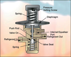
Figure 1: An automatic expansion valve (constant pressure)
Since the valve will have been set for a desired evaporating temperature, this will remain constant irrespective of system load. If the evaporator pressure were allowed to rise with an increase in thermal load, as with other types of refrigerant flow controls, the compressor efficiency would be greater due to higher suction pressure.
The constant evaporating temperature characteristic of this type of valve make it useful for small refrigerators and low-temperature storage cabinets.
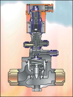
Figure 2: A cut-away of a thermostatic expansion valve
The automatic expansion valve can also be applied where the evaporating temperature must run close to 0°C without freezing. The hand-operated expansion valve always closes fully when the compressor is stopped as refrigerant liquid in the evaporator continues to vaporise with an attendant increase in pressure.
This ultimately overcomes the spring pressure causing the needle valve to close. When the compressor is started, the suction and evaporating pressure fall until the spring pressure opens the needle valve at the desired pressure setting.
Electronic expansion valve
The application of electronics to refrigeration and air conditioning systems has brought tremendous benefits to these industries offering a finer degree of control and system protection. The electronic expansion valve provides the following benefits:
• Precision refrigerant flow control using PI (Proportional-Integral) control algorithms
• Compensation for changes in liquid sub-cooling ahead of the expansion valve
• Rapid response to sudden and substantial changes in thermal load
• Low superheat levels allow greater utilisation of evaporator coil leading to maximum efficiency whilst maintaining adequate protection for compressor motor cooling
• Electrical connection between the key components offers greater flexibility with regard to positioning
Many electronic expansion valves utilise a modulating voltage signal from a controller to an actuator, which in turn controls the valve. As the supply voltage is increased, the pressure in the actuators container is increased and the increased valve opening permits greater refrigerant flow. Fine control results and the valve closes completely when the control voltage is removed.
Technology now available permits the valve to be precisely controlled by PWM (pulse width modulation). Over a period of six seconds, a signal is transmitted from the controller to the valve coil. This causes the valve to open and then close allowing a given amount of liquid refrigerant/saturated flash gas to pass into the evaporator and it is the relationship between the opening and closing times that determines the capacity of the valve.
At high thermal load, the valve will remain open for most of the six-second period and at low load, the valve will remain closed for the major part of the six-second cycle. When no refrigeration is required, the valve will shut altogether and act as a liquid-line solenoid valve.
Expansion valve hunting
Hunting describes a situation where a cyclic action of the expansion valve causes the evaporator to be overfed and underfed with liquid refrigerant. This results in a cyclic swing of refrigerant pressure and saturation temperature within the evaporator which in turn causes the average refrigerating capacity of the system to be severely reduced due to a generally lower suction pressure at the inlet to the compressor. Under extreme conditions, excess liquid refrigerant supply to the evaporator may lead to liquid flooding of the compressor with subsequent compressor failure. Hunting is caused by a number of possibilities:
1. High refrigerant velocity within the evaporator due to undersized tubes for the application causes the liquid refrigerant to pass through the coil in slugs which can pass through the evaporator into the suction line. The expansion valve bulb experiences a sudden drop in temperature as this liquid evaporates at a temperature well below the normal superheat value and causes the valve to quickly err toward the closed position. The reduced refrigerant flow that then occurs causes superheat to rise considerably, which then forces the valve to open widely with a sudden increase in refrigerant flow.
2. A time lag occurs between the change of valve position and the effect at the evaporator outlet (suction line) since the revised refrigerant flow rate will take some time to travel through the tubes of the evaporator coil before reaching the outlet where the bulb of the expansion valve can sense the new condition. There will also be a time lag between a change in temperature of the outer surface of the suction line and the change in the expansion valve overall bulb temperature leading to the increase/decrease in pressure within the bulb and the action upon the diaphragm within the valve. The time lag brought about by the combination of the above will lead to undershooting and overshooting of the desired condition with similar results on system efficiency. A solution to this problem is to increase the mass, and thus the thermal response, of the sensor bulb, which will damp the rate of temperature change and the valve’s ability to respond. This will either reduce or eliminate hunting altogether. thermal damping can be applied to air conditioning and refrigeration electronic control systems where outdoor fan speed must be varied to maintain a specified liquid line temperature at the outlet of condenser coils for low ambient control, particularly as the response rate of the electronic control system is virtually instantaneous, yet the effects of fan speed changes are considerably time lagged through the condenser coil and at the liquid line. The control software can also be written in a way that overcomes this problem.
3. Over-sizing of the expansion valve will also cause hunting since an excess amount of liquid refrigerant passing through the valve will cause sudden chilling of the bulb at the evaporator outlet, thus leading to sudden temperature drop at the bulb causing a rapid closing action at the valve. The much reduced refrigerant liquid supply, after time lag, causes excessive superheat, which eventually causes the valve to open, thereby supplying too much refrigerant due to excess over-sizing. Ensure that the valve is selected for the actual capacity rating rather than a nominal capacity value.
4.Incorrect sensor bulb positioning can also lead to expansion valve hunting. If the bulb is located on a vertical outlet header connecting two or more evaporator coils, liquid may overflow a coil from above thereby chilling the bulb. The bulb should always be located on the horizontal outlet pipe from the coil to ensure this situation cannot arise. Locate the bulb as close to the evaporator outlet as possible. The bulb must not be located on the underside of the suction line. The manufacturers’ recommendations must be followed and these may specify the 3 or 9 o’clock position or 45° between the side and underside of the suction line. Insulate the bulb/suction line with high quality insulation that is impervious to water vapour, particularly on low-temperature systems where the presence of moisture will lead to freezing and incorrect bulb response. A cross-charged sensor bulb will also reduce the effects of hunting (see last month’s article for details of cross-charged expansion valves).
Charge migration
The refrigerant liquid passing through the expansion valve experiences a dramatic drop in pressure and flash gas is produced as part of the liquid evaporates. This causes the body of the valve to be continually chilled. Heat is conducted from the diaphragm assembly above the valve body leading to a drop in temperature of the refrigerant charge within the diaphragm housing. Under certain circumstances, this housing can fall to a temperature that is lower than the temperature at the sensor bulb. If this situation arises with a gas-charged valve, the majority of the charge will condense within the diaphragm and control of the valve will then be transferred to this point rather than at the bulb. These conditions will give rise to severe restriction of refrigerant flow to the evaporator coil and may also lead to complete shutting of the valve since the very low and almost equal temperature/pressure on both sides of the diaphragm will allow the spring to close the valve.
Gas-charged valves should therefore only be used where there is a reasonable pressure drop between the valve outlet and the suction line leaving the coil. The presence of a distributor will ensure this is the case as will a coil of high pressure drop. Under these conditions, the valve body will be at a higher temperature than the bulb because the higher pressure at the valve will bring about a higher saturation temperature than that at the coil outlet by the bulb. Any migration will be towards the bulb, which will thereby retain control over the valve.
Distributors
The purpose of a refrigerant distributor is to provide an equal supply of liquid/saturated vapour refrigerant to a number of outlets which in turn feed a multi-circuit evaporator coil. The preferred mounting position is vertical with refrigerant flowing downward to ensure gravity does not influence distribution thereby causing uneven flow although it is accepted that this effect will be minimal. There are various types of distributor including venturi, centrifugal, pressure drop and manifold arrangements. All perform the same function.
It is advisable to use an externally equalised thermostatic expansion valve when a distributor is employed to compensate for the overall pressure drop through the distributor and evaporator coil.
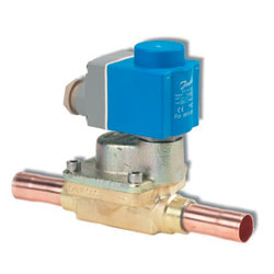
A type of expansion valve manufactured by Danfoss
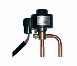
A type of electronic expansion valve manufactured by danfoss
Flooded evaporators
A flooded evaporator is continually full of liquid refrigerant which leads to greater performance and efficiency as opposed to dry evaporator types where a mixture of saturated liquid, considerable saturated vapour and partial superheated vapour exist. The high liquid content leads to greater heat transfer to the body of liquid refrigerant from the air passing over the coil. Flooded evaporators are normally restricted to larger air conditioning and refrigeration systems.
Some form of control is required to maintain the evaporator full of liquid refrigerant and a reservoir (accumulator) adjacent to the evaporator is also required to provide a store of liquid refrigerant. The control normally takes the form of a float valve and this can be positioned at the inlet to the reservoir (high side) or in the evaporator or within the accumulator itself (low side). A liquid pump is employed to continually recirculate the liquid refrigerant from the accumulator to the evaporator. Excess liquid refrigerant is returned to the accumulator.
With thanks to Mike Creamer of Business Edge who revisits his Masterclass series of articles, updating and adding to the information which proved so useful to readers when the series was first published over ten years ago. In this reincarnation, the series will cover both air conditioning and refrigeration and serve as an on-going source of technical reference for experienced personnel as well as providing a solid educational grounding for newcomers to our industry.