Mike Creamer of Business Edge revisits his Masterclass series of articles, updating and adding to the information which proved so useful to readers when the series was first published ten years ago. In this reincarnation, the series will cover both air conditioning and refrigeration and serve as an on-going source of technical reference for experienced personnel as well as providing a solid educational grounding for newcomers to our industry.
In recent issues we have addressed the principles behind continuously variable capacity systems. Most manufacturers offer a wide range of variable refrigerant flow air conditioning systems, many of which share some similarities of design and functionality. However, there can be slight variations upon the basic structure with regard to elements of design, including capacity control, compressor type, control software and systems, refrigerant, pipe design and limitations amongst others; and in the following series of articles we hope to clarify the subtle differences between the range of products available from a variety of manufacturers.
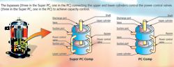
Fig 1
Sanyo ECO Multi
This variable refrigerant flow system was first introduced in the early 1980s as a two-pipe heat pump system. However, the Eco Multi range has undergone development since this time. The latter part of the decade saw the introduction of the first three-pipe simultaneous heating and cooling system.
As with many manufacturers the variety of products available to the market includes a wide range of equipment starting with the 8hp two-pipe heat pump models up to the large 48hp heat pump models. This is achievable through the addition of a second outdoor unit which in turn allows up to 40 indoor units to a single system from 24hp upwards, operating with a diversity ratio of between 50 and 130% of the outdoor unit's capacity.
Units are also available with heat recovery, with outdoor unit capacities of between 8 and 16hp and system configuration from 8 to 48hp. These systems offer simultaneous heating and cooling where independent mode control is required. A wide variety of options are available when selecting indoor units, these include semi-concealed type (4-, 2- and 1-way discharge), ceiling mounted, wall mounted, floor standing and concealed floor standing as well as above-ceiling ducted units. For all applications manufacturers offer a unit to suit the application and desired location.
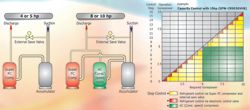
Fig 2
To make things simple all the indoor units are standardised. In this way the same indoor units that are used for the VRF product are also used with the split system range. What this offers is commonality of controls and aesthetics. All the indoor units have sophisticated electronic controls, including electronic expansion valves offering accurate and precise temperature control.
Capacity control
To achieve the varying load requirements that multiple indoor units place upon the connected outdoor unit, Sanyo developed a Power Control twin rotary compressor that varies its internal cylinder volume. In this way the compressor can be controlled at 25%, 50%, 75% and 100% load levels, this coupled with an external 'save' valve (hot gas bypass) gives capacity control at 12.5%, 25%, 37.5%, 50%, 62.5%, 75%, 87.5% and 100%. Illustrations of just how this is achieved can be seen in Fig 1 and 2.
When controlling the larger outdoor units (8hp and upwards), additional compressors are installed within the refrigeration circuit, stage capacity loading can be achieved by loading the Super Power control compressor and turning on the constant load compressors to enable the demand from the indoor units to be equally matched.
Along with the varying capacity compressor, load control is fine-tuned by means of an electronic expansion valve installed within the indoor unit. Each indoor heat exchanger has three temperature sensors installed; these are constantly monitoring indoor coil temperature and adjust the electronic expansion valve to maintain predetermined temperature differentials. Fig 3 shows how variance in capacity is achieved within the systems offering simultaneous cooling and heating.
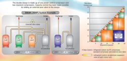
Fig 3
As the return air temperature becomes closer to the desired target set point, demand requirement from the indoor unit is reduced, this signals for a reduction in compressor demand capacity and also reduces the indoor expansion valve opening orifice, and this will lead to reduced refrigerant flow through the heat exchanger and therefore a reduction in indoor unit capacity. At the point where target set point is reached the indoor unit signals to the outdoor unit for no load demand, and the internal expansion valve closes to a minimum position, usually 20 pulses. With the expansion valve now closed no further refrigerant can flow through the heat exchanger, the indoor unit now operates at a condition of fan-only, awaiting the 'system on' demand.
With the above control pattern, combining the compressor varying output and the temperature controlled electronic expansion valve, space temperatures can be maintained with low fluctuating temperature values, unlike conventional ac systems where the compressor cycles on and off in conjunction with the space temperature requirements. Along with efficient temperature control, energy efficiency is also improved, low starting currents are obtained with the compressor being fully unloaded at start-up. While varying the compressor capacity, electrical usage is reduced unlike conventional systems having their compressor operating at full load running current whenever the compressor is operating. Fig 4 gives details of the compressor control along with information regarding the 16 steps of capacity control.
Unlike a normal split system, selecting a VRF system is not a simple off-the-shelf purchase. VRF applications need to be correctly designed and are often sized with the indoor units accounting for some 130-150% of the capacity of the outdoor unit. This combination can then be applied to condition areas where the peak loading may only be for short periods of time, or in north/south facing buildings where the load patterns change throughout the day.
One of the advantages of VRF systems is the facility for large separation distances between the indoor and outdoor units, with most systems offering pipe runs of up to 100m. As with all refrigerant pipework, when installing and carrying out any brazing it is vital to pass a small positive charge of oxygen-free nitrogen through the pipework, prior to, during and, for a short period, after brazing. This prevents any oxidisation occurring inside the pipework which can lead to internal strainers becoming blocked.
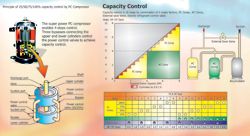
Fig 4
Control wiring configuration
As with the majority of products that originate from Japan, electronics play a major role and, in the case of the VRF system, it becomes apparent when looking at the control system.
As with the refrigerant pipework where a network is formed, the same applies to the control system. Starting at the outdoor unit, a two-core communications cable (non-polarised) is installed from the outdoor unit to the first indoor unit; this is then continued in a daisy chain fashion from the first indoor unit to the second, third, fourth, etc.
If more than one system is to be controlled from the same point, a larger network can be created. To achieve this, the outdoor units can also be connected together in a daisy chain fashion.
In this case each outdoor unit is given its own electronic address number. Once this number has been given it allows control communication of many systems operating on the same network. Along with the indoor to outdoor control network, local control wiring has to be considered. Various options are available at this stage, a simple individual remote controller per indoor unit is a common option.
Group configuration is often chosen for open plan areas where more than one indoor unit is to be controlled from the same remote controller. Another option also available is to have a central system controller that controls all the installed indoor units from one control point. This can eliminate the need for local remote controllers. Some advantages with this option are: reduced costs due to fewer installed controls, easier installation process and less installed control wiring.
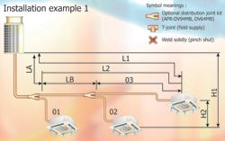
Installation 1
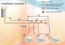
Installation 2
With larger installations it is now common practice to include computer control systems, these can be dedicated systems controlling just the installed VRF product, or vast BMS systems that incorporate all building control functions. In most cases to achieve this requirement interface gateways or software protocol converters are installed, this allows all the required systems (fire alarms, boilers, lighting, etc) to communicate at a common level.
Commissioning procedure
After the installation has been completed, consideration has to be given to the commissioning and start-up of the system. As with all air conditioning, refrigeration and heat pump installations, the pipe work must be pressure tested in accordance with BSEN 378/2008. This procedure is carried out by pressurising the installed pipe work with a suitable inert gas, such as oxygen-free nitrogen.
An allowance must be made, when checking for any pressure drop, to allow for any ambient changes within the test period. After a satisfactory pressure test, the next stage is evacuation. The preferred method is the triple evacuation method, whereby a vacuum is pulled on the system. This vacuum is then broken with a positive charge of dry nitrogen, (this process is repeated three times) in this way any moisture within the pipework is diluted by the nitrogen speeding up the evacuation process. The final stage of the process is to leave the vacuum pump running to achieve a suitable level of vacuum, again in accordance with BSEN 378/2008. For example 2.7mBar or 2 Torr or below.
Once the pipe work has been evacuated, any additional refrigerant required can be weighed into the liquid line. This is often known as 'bomb charging'. As the pipework is still under a vacuum condition the additional charge can be added very easily and, as with most 'blend' refrigerants, this allows the charge to be added in the correct manner, in the liquid phase.
Prior to turning on the power supplies, ensure all electrical connections are tight and all connection plugs are located correctly. Check and locate the respective power supplies, check for correct MCB/fuse ratings and cable sizing including all earth connections.
In the case of the Eco Multi, two settings need to be made at the outdoor unit before turning on the power: the outdoor unit's electronic address number and the connected number of indoor units. The power can then be turned on and an auto address procedure is carried out. This electronically labels each Indoor unit with a dedicated electronic address, comprising the refrigerant system number and an Indoor unit number. This obviates the need for dip-switch settings or the like at the indoor units.
After this procedure has been completed and the crankcase heaters have had sufficient time to warm the compressors, the systems can be started and checked for correct operation. Operating each indoor unit in each mode, and monitoring operating temperatures, running currents etc; this can be achieved by viewing these values from either a remote controller, or using the manufacturer's 'service checker'. The service checker comprises a PC connected to the system via the indoor to outdoor communications cabling. A log can then be made of real time values and the system can then be analysed for correct operation.
Service and maintenance
As with all air conditioning systems, service and maintenance is a must to ensure correct system operation and to ensure a long operating life. Like most VRF products, if the systems have been installed and commissioned correctly, very little goes wrong, but one major factor that affects all air conditioning systems is cleanliness. Regular filter cleaning and external and internal cleaning is a must. An annual coil clean is also recommended; this is often a chemical clean that also doubles as a disinfection of the internal heat exchangers and drip tray assembly. Flushing of the condensate pump and checking for correct operation should also be high on the maintenance checklist.
The VRF System will also have to be leak- checked in accordance with EC regulation 842/2006 (the F-gas regulations). This may require direct or indirect testing to be carried out either once or twice a year depending upon the amount of refrigerant within the system. If a direct leak check cannot be carried out on the system due to installation constraints then the indirect approach must be adopted. This entails operating the complete system in its various operating modes, checking for correct operating temperatures, running currents and the like is usually sufficient to gauge if the system is operating correctly. As with the commissioning procedure, when carrying out this work, attaching the service checker or a third party system performance analyser to the system and logging the operating conditions is very useful. This information can be compared to the data that was taken when the system was first commissioned and will then identify if the system has deteriorated in any way.
______________________________________________________________
Sanyo update to Part 63
Sanyo has informed us of a number of updates and improvements to its ECO series of VRF units which were featured in Part 63 of Masterclass above.
The ECOi Series 6 VRF launched last year became the first VRF in the market to be configurable to operate in either ultra high efficiency mode or high performance mode.
Standard mode offers the highest capacity while still delivering excellent efficiency, while hi-COP mode delivers exceptional efficiency and low running costs with a slight reduction in capacity.
In ultra-efficient mode the 8hp unit boasts a COP of 4.57 - an improvement of 11% on the previous class leader. Across the range, COPs are in the region of 4.45, with a SEERs in excess of 6.2.
Operating range has also been extended, enabling the Series 6 to provide heating at ambients as low as -25ºC. Maximum pipe lengths have been extended to 1000m with a maximum of 64 indoor units supplied from a 107kW duplex outdoor unit.
Available as an R22 Renewal version, it becomes a rapid and low cost way of replacing old R22 units with the new R410A verison. R22 Renewal can be used with virtually all types of R22 systems from other manufacturers and can also be applied to existing R407C systems.
Existing wiring can also be used on most installations. It is equipped with refrigerant charge prediction, for accurate and quick charging - giving performance optimisation and enhanced energy efficiency - and offers extended compressor life with automatic run-time sharing.
It can also provide low temperature cooling, down to 10ºC , making it suitable for applications such as food processing or industrial process applications.
Condenser fans in the Series 6 have been redesigned to significantly reduce turbulence and improve their mechanical and aerodynamic efficiency. The fan is able to operate with a higher speed and greater efficiency, but still deliver the same low noise levels as before.
The shape of the impellers on the Series 6 fan have been redesigned to distribute mechanical stress more evenly. The result is greater power, improved reliability, and better energy performance.
The DC-inverter controlled system features a new high external static pressure fan, made possible by an improved fan blade, motor and casing design - delivering up to 80Pa.
Heat exchange performance has also been significantly improved through a combination of redesigned coils and new fan design. Airflow volume through the coil has been increased by 2.2% and the weight of metal used in the heat exchanger has been reduced by 30%.
The internal design of the oil separator has also been dramatically improved in the Series 6 further improving the effectiveness of heat transfer.