Over the last few months we have been reviewing the various VRF systems available from manufacturers. While all these systems are generally similar in what they do, there are minor differences in terms of the control, piping arrangements and components when comparing one product line to another.
Before continuing with a review of the product line and technology from another well-known manufacturer, we will look at some of the site situations and problems that may arise during the lifetime operations of such systems and how these can be dealt with.
What can go wrong?
VRF multi-split systems comprise a number of indoor units, distribution boxes within the building and a central station outdoor unit. Consequently, such systems therefore include the following:
· Long refrigerant pipe runs, both horizontal and vertical
· Indoor units above outdoor units and vice versa
· A large number of mechanical joints
· A large number of brazed joints
· A substantial refrigerant charge
· A reasonable charge of lubricating oil
· A large number of microprocessors and interconnecting wiring
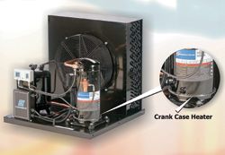
Fig 1: the position of a crankcase heater fitted
to the compressor of a multi-split system
Given the extensive list above, it is quite clear that reasonable care and attention must be paid to every aspect of the installation of VRF systems if these are to work satisfactorily during start-up and commissioning. If not, the time and money spent in detecting the cause of problems/malfunctions can be considerable, following which rectification work then has to be undertaken, normally at the installer's cost.
Even if the installation, start-up and commissioning runs smoothly, followed by months or even years of satisfactory operation, problems will arise, driven by events such as component failure, an electrical/electronic problem, refrigerant leakage and so on.
If equipment is not adequately serviced and maintained on a regular basis by professional refrigeration engineers, the incidence of such problems will undoubtedly rise. Even where systems are well serviced and maintained by professionals, things will inevitably go wrong from time to time.
The following are simple problems that might arise on such systems. The work in detecting these defects and the work in rectifying them may not be so simple.
The crankcase heater
Fig 1 shows the crankcase heater fitted to the compressor of a multi-split system. Let us first consider the function of this component.
While the system is in operation, the heat generated by the compressor motor maintains the lubricating oil within the sump, or crankcase of the compressor, at a reasonably high temperature of at least 25°C or above, according to operating conditions.
The lubricating oil passes through the bearings and other parts of the compressor mechanism, and friction also maintains the temperature. The refrigerant vapour passing through the compressor mechanism, a scroll compressor in the example, carries a proportion of oil with it, and during the compression process, the refrigerant is raised extensively in temperature and any oil mixed with the refrigerant during the process is also substantially heated.
Some compressors incorporate an integral oil separation facility that ensures that a high percentage of oil is returned to the crankcase, leaving the compressed refrigerant in the compressor relatively oil free. Many multi-split systems incorporate an oil separator. Refrigerant vapour, containing a percentage of oil, leaves the compressor and passes through the oil separator. Such separators can be extremely high in efficiency and, if well designed, will remove 99.5% or more of the oil entrained within the refrigerant vapour. The oil that is separated falls to the base of the oil separator, which is usually a cylindrical vessel standing vertically.
An oil outlet connection at the base of the oil separator is connected directly to an appropriate port for oil return at the compressor body. Given that the oil separator is under high discharge vapour pressure and the crankcase of the compressor experiences low vapour pressure, the differential pressure between these two is sufficient to drive the lubricating oil from the separator to the oil return port of the compressor.
In order to prevent high-pressure discharge vapour from the compressor simply re-circulating back to the compressor oil return via the oil separator, a capillary tube within the oil transfer line is employed. Other systems, for example supermarket refrigeration systems, have a more sophisticated arrangement for oil return to the compressor. Under normal operating conditions, therefore, the majority of lubricating oil should remain within the outdoor unit. This is highly desirable, since excess circulating throughout the refrigeration pipework, distribution boxes and indoor unit is simply being pumped around the system for no good reason, while consuming power and reducing system capacity. Moreover, excess oil lining the tubes of the indoor heat exchangers reduces the thermal transfer efficiency of these items. This results in:
· Reduced cooling/heating capacity
· Increased power input
· Reduced COP
· Extended run times
Some systems also incorporate a suction accumulator, which sits upstream of the inlet to the compressor. This vessel will ensure that any excess liquid returned to the outdoor unit is first collected within the suction accumulator and then drawn off as vapour into the compressor, rather than liquid refrigerant which otherwise might cause serious mechanical damage to the compressor.
The suction accumulator can also accumulate oil and some systems incorporate a means of returning this oil from the base of the accumulator to the crankcase of the compressor.
Function of the crankcase heater
We have already established that when the compressor is running, the temperature of the oil is raised considerably above both the ambient temperature and the air temperature surrounding the indoor units. When the compressor switches off, there is considerable residual heat retained within the mass of the motor windings and compressor mechanism, and the oil therefore remains at elevated temperatures for a considerable time.
Many systems employ an insulation jackets around the compressor. The primary purpose of this is to ensure that the heat generated within the
compressor is transferred to the refrigerant for subsequent rejection at the indoor units when in heating mode, thus maximising system efficiency, COP, whilst reducing run times and overall power input.
This insulation jacket is also, of course, valuable at keeping the oil at elevated temperature during compressor off-cycle periods.
So why is it important to maintain the oil at an elevated temperature? Many cooling-only air conditioning systems run when outdoor ambient temperatures are higher than the indoor temperature. There are of course systems that are still required to run when the outdoor temperature is lower than this internal design temperature and this is due to the generation of heat energy from high levels of occupancy, lighting, machinery, solar gain and so on. It is unusual for such systems to run in cooling mode when the outdoor temperature is extremely cold. Exceptions to this are of course when the application is not one of comfort cooling, but one of process cooling or cooling of electronic loads that run 24hrs/day.
Where a system is required to run during periods of low outdoor temperature, it is necessary to consider what will happen from when the system switches off. The system will switch off if the indoor temperature has been satisfied, or may also be forced to an 'off' condition via time control during the night or over weekends.
In such circumstances, the oil in the compressor crankcase gradually cools to match that of the prevailing outdoor temperature. Under such circumstances, the outdoor unit component and the oil will fall to a temperature below that of the indoor units and system pipe works, especially as the building is normally well insulated and its temperature falls much more slowly than that of the outdoor unit.
Under these circumstances, refrigerant will always migrate and a proportion will form as liquid within the coldest regions of the system, in most cases, this being the outdoor unit. If the temperature of the oil is also very low, the liquid refrigerant will form over the oil and will be absorbed within the oil over time.
During an extensive 'off' period, oil will progressively drain from the upper parts of the compressor mechanism, bearings and so on, to the crankcase. If the system is off for a weekend, a high percentage of oil may drain from the upper regions of the compressor.
During this off-cycle period, the high and low pressure regions of the system are likely to equalise completely. When the system is restarted, the compressor will progressively generate high pressure throughout the discharge regions of the systems and will rapidly generate a low suction pressure at its inlet and the suction pressure regions of the system.
As the refrigerant pressure above the oil rapidly drops, the liquid refrigerant entrained within the oil starts to evaporate rapidly. This causes a severe drop in temperature within the body of the oil, which increases its viscosity and thus reduces its ability to flow freely.
Moreover, the bubbling action of the boiling refrigerant causes the oil to change from a fluid condition to a foam condition.
These two factors, reduced viscosity and foaming, have a severe effect on the ability of the compressor pumping mechanism to draw the oil from the crankcase and transfer it to the vitally important regions of the compressor, such as the main shaft bearings, scroll mechanism bearings, compressor mechanism surfaces, and so on.
If the compressor has been held 'off' under time control, it may be necessary for it to run for an extensive period in order to satisfy the temperature set point within the building. Any extensive running with dry or poorly lubricated bearing surfaces will cause serious damage to the compressor bearing, and finally, machine surfaces. The results of this damage will manifest themselves in the following ways:
· Reduced compression capability resulting in loss of capacity, reduced COP, increased power inputs and extended run times
· Accelerated wear and reduced life on bearings and compressor mechanisms
· Compressor seizure through rapid overheating and expansion of bearing surfaces. Such seizure could also cause the compressor motor to overload and fall with short circuit windings, open circuit windings, or down to earth.
· Where motor failure occurs, there is also the risk of damage to power inverters/speed controllers driving the compressor motor.
If the compressor is repeatedly started under such conditions, say every weekend, a small amount of damage might be applied to a given bearing, ultimately leading to complete failure.
Many scroll compressors employ roller bearings for the main shaft, and a sleeve bearing for the compressor mechanism at the top of the compressor is the most vulnerable should the lubrication system not be functioning correctly.
Moreover, roller bearings are very tolerant to a lack of lubrication for a short period of time. This is not the case with sleeve bearings. Given that this is the type of bearing that might be found at the top of a scroll compressor, a lack of lubrication at this point must be avoided at all costs.
The solution
Fortunately, the solution to this potentially serious problem costs only a few pounds and consumes only 60W of power. The crankcase heater can be energised every time the compressor is switched off, and simply maintains the oil at a sufficiently high temperature to prevent the migration of refrigeration vapour and condensation of liquid refrigerant within the body of the oil. In order to avoid excess energy consumption, some systems simply switch the crankcase heater on when the compressor is switched off. Other systems leave the crankcase heater in operation at all times.
Given the above, it is vitally important to ensure the crankcase heater is actually working. It is also essential to ensure that the crankcase heater is not live when you commence work on the outdoor unit, or the condensing unit of a standard air conditioning or refrigeration system. The crankcase heater may have been permanently wired on a separate isolator so that this remains live even though you have taken the precaution of isolating the outdoor unit.
Crankcase heaters can also suffer from an intermittent type of failure where they will provide the essential heating some of the time, but not all of the time. This is a difficult one to detect.
Reserve cycle heat pump systems
Single and multi-split heat pump systems are required to run during low ambient winter conditions by the very nature of their application.
These systems are most vulnerable to crankcase heater failure since it is likely that they will be switched off during the night and over the weekend, and very low ambient temperatures, and indeed sub-zero conditions will prevail around the outdoor unit. Under such circumstances, refrigerant will migrate and form within the lubricating oil, and if the crankcase heater is not working correctly, the risk of compressor failure is exceptionally high.
With thanks to Mike Creamer of Business Edge who revisits his Masterclass series of articles, updating and adding to the information which proved so useful to readers when the series was first published over ten years ago. In this reincarnation, the series will cover both air conditioning and refrigeration and serve as an on-going source of technical reference for experienced personnel as well as providing a solid educational grounding for newcomers to our industry.