However, in some instances, the principles behind their selection have not been covered. Therefore, before proceeding further into capacity control and the specific aspects of refrigeration and ac, we will now look at a complete system to summarise the content of certain preceding articles.
Most of the components discussed so far are shown in the drawing shown in Fig 1 (overleaf).
Control systems
Control systems can be classified into three categories:
1. Controls necessary for the correct operation of the system
2. Controls that make a system safe
3. Controls that ensure the correct design conditions within the conditioned space or products are achieved.
An examination of Fig 1 shows a typical refrigeration plant that consists of an air-cooled, multi-fan condenser connected to two compressors operating in parallel, which in turn are connected to three evaporators. Each of the evaporators are connected to an individual thermostat which in turn is connected to a solenoid shut-off valve fitted in the liquid line feed to each of the thermostatic expansion valves. Each compressor is fitted with a differential pressure oil safety switch that is subjected to the discharge pressure generated by the compressor mechanical oil pump and the pressure within the compressor crankcase at the suction inlet of the pump.
The system is fitted with a safety high pressure cut-out switch, low pressure cut-out switch and a control suction pressure switch.
All the major system components are fitted with hand shut-off valves to enable them to be isolated. Any components which can be isolated with refrigerant trapped inside are fitted with pressure relief valves.
The major refrigerant containing components vent their safety relief valves to atmosphere while components containing a smaller refrigerant charge are arranged to relieve to the system low side. The low side can ventilate to atmosphere also if necessary.
The system incorporates an evaporator pressure regulator and a suction line accumulator. A capacity regulating valve and liquid injection valve are also included.
If we follow the flow of the refrigerant from the receiver through the system we will encounter the three categories of control referred to earlier.
The first component in the flow path is a shut-off valve. This component is frequently selected on the basis of the refrigerant line size but there are many types of shut-off valve ranging from ball valves to globe valves each with its own characteristics which include the pressure drop through the valve, positive shut off, spindle and gland gas tightness. Some of these characteristics change according to whether the valve is fully open or fully closed.
Generally a ball valve is recommended for fitting as a normally open valve. It has little or no pressure drop if it is selected on the basis of its bore matching the pipe line. It is therefore particularly suitable for suction lines.
Where positive shut off is a primary requirement, then globe valves or “Y” type shut-off valves may be more suitable than ball valves.
Hand shut-off valves that are normally fitted for maintenance purposes only and are not used during normal operation of the plant should be fitted with a vapour tight cap. Not only does this solve the problem of potential refrigerant leakage through the spindle gland, it also deters unauthorised personnel from changing the valve position.
The valve caps must comply with BSEN 378 in that they must be able to relieve any pressure that may have built up under the cap, due to leakage, in a safe and controlled manner. This usually consists of a small hole drilled into the threaded section of the cap and as the cap is unscrewed the hole is exposed. This feature would also reveal whether or not the spindle gland is intact and help prevent the removal of the cap which could result in a significant vapour leak.
The next component encountered in the flow is the refrigerant drier, a component which has increased in importance due to the introduction of the new range of refrigerants and their associated requirement for synthetic-ester oils. These oils are particularly hygroscopic and if incorrectly handled can introduce significant amounts of moisture into the system.
Drier selection
• Ensure drying medium is suitable for the refrigerant in the system. (NB: some manufacturers have reservations about the use of driers containing activated aluminium with systems containing HFC refrigerants.)
• Ensure drying medium is suitable for the type of oil in the system.
• Select drier on the basis of system duty and volume of system charge.
• Check pressure drop through drier at design duty.
Direct expansion systems that operate with a near constant load, or use high-side float control will have a relatively small refrigerant charge for a given duty.
Systems that have large load variations or incorporate flooded evaporators or are of the pumped circulation type will have a large refrigerant charge for a given duty.
The latter type of system should have the largest drier core capacity for its specified duty.
The next component is a pressure relief valve. If the liquid line contains liquid refrigerant which is sub-cooled below ambient temperature and if it is also possible to trap this liquid between two isolating devices (shut-off valves, solenoid shut-off valves) then when the liquid warms up, it will expand.
As there will then be insufficient space for expansion, the refrigerant will rupture the weakest point, in this case the drier assembly. BSEN.378 therefore recommends that a pressure relief valve be fitted in order to protect the assembly from rupturing with potential for personal injury.
Pressure relief valves, as opposed to other forms of pressure safety devices such as bursting disks and fusible plugs, have the ability to reseal themselves once the excess pressure has been discharged.
The re-sealability of a pressure relief valve permits discharge from one side of a component to an area having a lower pressure and the ability of the valve to reseal itself prevents any possibility of reverse flow taking place, or indeed continuous by-pass to then occur. This is illustrated in Fig 1.
The next component is the liquid to vapour heat exchanger, sometimes referred to as a suction-liquid interchanger. The primary purpose of this component is to sub-cool the liquid refrigerant thereby improving system cooling capacity without power input penalty.
As a consequence of sub-cooling the liquid, the suction refrigerant vapour is super-heated and this reduces the amount of liquid entrained in the vapour. This latter feature can be useful when the suction lines are short as this will reduce sweating at the compressor.
To calculate the amount of heat transferred from the liquid side to the suction vapour the following formula can be used:
Q = k x A x tm
Where Q = heat flow (Watts)
k = heat transfer coefficient (W/m2°C)
A = Transfer area of heat exchanger (m2)
tm = Average temperature difference (K)
[tm = (tmax – tmin ) / lnternal (tmax ÷ tmin )]
The liquid to vapour heat exchanger must not be oversized since excessive superheating of the refrigerant suction vapour will increase specific volume thereby reducing mass flow through the compressor. Inadequate cooling of the compressor motor in the case of semi-hermetic compressors would also result.
Liquid line solenoid valve (LLSV)
We now arrive at the liquid line solenoid valve (LLSV). This valve facilitates the evacuation of liquid from the evaporator during the off-cycle, ie when the thermostat de-energises the solenoid valve on reaching its set temperature. This valve provides a back-up safety feature by preventing liquid leaking through the TEV during the off-cycle.
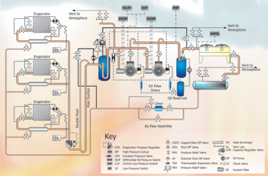
Figure 1: a typical plant that consists of an air-cooled, multi-fan condenser connected to two compressors operating in parallel, which in turn are connected to three evaporators
Liquid line solenoid valves are selected on the basis of the evaporator duty expressed in kW for a specific refrigerant and the maximum operating pressure differential (MOPD). This is the highest pressure that will occur on the inlet to the valve minus the lowest pressure that will be found on the outlet of the valve. This MOPD must not exceed the manufacturer’s rating if the valve is to open correctly.
When reading selection data, ensure that it applies to the fluid passing through the pipe as it is not unknown for an engineer to select a valve for suction line use whilst reading data for discharge flow. On larger plant it is well worth considering the use of solenoid valves fitted with a manual opening spindle. This is useful when diagnosing possible problems in the control circuit or proving the correct operation of the valve. With this type of solenoid valve, the stem, 53, is screwed clockwise to manually open the valve. The stem lifts the valve seat, 83, allowing fluid to pass through the valve (see fig 2)
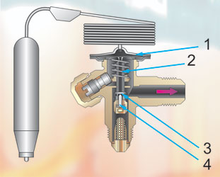
Figure 2
Thermostatic expansion valve
We now reach the thermostatic expansion valve. These valves are available with a number of functions which allows the requirement of a system to be closely matched. Further data on expansion devices is available from within preceding articles.
Readers of this series will already know that a TEV modulates open or closed in response to temperature variations at the evaporator suction outlet pipe/TEV phial strapped to the pipe. As the temperature increases, the pressure generated by the TEV phial refrigerant charge increases and this pressure is transmitted onto a diaphragm. The diaphragm bows and moves a push-rod that opens the inlet to the valve, thus allowing refrigerant to enter the evaporator. The current evaporating pressure, which continually varies with instantaneous load, is transmitted to the underside of the diaphragm. The difference between these two, coupled with the action of the spring, allows the control of superheat. When the temperature falls, the pressure difference above and below the diaphragm is reduced to zero (the pressures on the diaphragms upper and lower surfaces are in equilibrium) and the only differential pressure now exerted is that generated by the superheat adjusting spring which closes the valve (see fig 3).
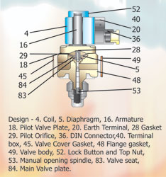
Figure 3
The type of valve shown is an internally equalised valve. These valves are used when the pressure drop across the evaporator is less than 0.25 bar. When the evaporator pressure drop exceeds 0.25 bar, an externally equalised TEV is used. These valves have an external connection between the TEV and the evaporator outlet and this ensures that the pressure at the evaporator outlet is exerted on the underside of the diaphragm rather than that at the inlet which will be higher thus leading to inaccurate control of superheat. If the temperature at the outlet is greater than the saturated pressure-temperature relationship then superheat will warm the phial and raise the pressure within the phial and start to modulate the valve open.
When calculating the pressure drop across the evaporator, the calculation should cover the run from the expansion valve outlet to the evaporator outlet. Since all but the smallest evaporators will be fitted with distributors and distributor tubes, the pressure drop in these components must be taken into consideration. Typically these components are selected on the basis of a pressure drop of 0.5 bar.
TEVs are selected on the basis of the evaporator duty, the type of refrigerant and the pressure drop that occurs between the receiver outlet and the evaporator inlet. While on most air conditioning and single stage applications the amount of liquid sub-cooling will be insufficient to affect the valve selection, it should be born in mind that when mechanical sub-cooling is used, this can have a significant effect on the valve capacity and must be taken into consideration during the selection process.
Evaporator pressure regulator
The next component is an evaporator pressure regulator. Although it would be unusual to find both an EPR and a Capacity Regulator (CPR) on the same system, it is not totally unknown. The EPR senses the evaporator pressure and modulates to close the suction line when the evaporator pressure starts to fall, while the CPR valve by-passes discharge gas into the suction when suction pressure falls. In the configuration shown as Fig 1, the CPR valve is sized to match the duty of one evaporator or 1?3 the installed compressor capacity. This would be adequate to prevent short cycling and at the same allow a reduction in pressure of the suction side when the load on the second evaporator begins to fall, thereby enabling a pressure sensor to switch off one compressor.
Although the suction pressure would fluctuate upstream of the EPR, the pressure downstream of the EPR would be maintained at a constant level thereby maintaining a constant evaporation temperature. If the pressure continued to drop upstream of the EPR, then the system controller would switch off one of the compressors.
The function of the discharge by-pass capacity pressure regulating valve (CPR) and its associated de-superheating expansion valve was covered in last month’s article. An examination of Fig 1 shows that a dual pressure relieving valve (PRV) assembly is fitted to the suction line accumulator. Since the low side can be isolated from the high side and some high side relief valves are venting into the low side, precautions must be taken to protect the system if a fire occurred. Therefore, a relief valve assembly of sufficient capacity must be fitted to the low side. The location of this PRV can be anywhere on the low side as long as the connections to the PRV are of sufficient size to allow vapour to vent through and the PRV cannot be isolated from the system. Mostly, this would be from a suction line accumulator or suction header if one is fitted.
Oil separators
Fitting an oil separator is to reduce the amount of oil carried over into the system leading to reduced oil level in the crankcase of the compressor(s). This oil is entrained in the discharge gas as it is pumped from the compressor(s). It should be noted that oil separators reduce the amount of oil carried over into the system, no oil separator is guaranteed to be 100% efficient.
Oil is required to lubricate the moving parts of the compressor. It is not required anywhere else in the system. Oil is an insulator and in fact reduces the efficiency of all the heat exchange surfaces that it comes into contact with. Moreover, it can be argued that a small percentage of the energy expended by the compressor is dedicated to pumping this oil and that the overall mass flow of refrigerant throughout the system is reduced.
Oil separators which are connected to condensers that are located vertically above them should be fitted with a check-valve in their outlet . This check valve is to prevent liquid refrigerant that can be condensed in the discharge line to the condenser, draining back into the separator and mixing with the oil. If this occurs, refrigerant rich oil is fed back to the compressor where the oil will foam. This will displace the oil from the crankcase. When this occurs, compressor lubrication fails and the compressor either will trip out via the safety switch or more seriously, the bearings will be damaged. Systems that have long off cycles, particularly during winter, should have a heater fitted either in or around the oil separator. This heater will evaporate any liquid refrigerant that condenses within the separator. The heater should be inter-locked with the motor contactor arranged to energise the heater whenever the compressor motor switches off. This can be achieved via the auxiliary contacts of the contactor. Most conventional oil separators separate the oil from the discharge vapour by reducing the velocity of the vapour to a level which is below its ability to carry droplets in the vapour stream. The discharge vapour then passes through a mesh which assists in the removal of the oil droplets and at the same time acts as a filter to remove any sediment that may be in the system. With this type of separator it is important not to exceed the design capacity of the separator, otherwise the correct oil drop out velocity will not be achieved.
Whilst the above method of oil separation is possibly the most common, there are other types of oil separators which operate on different principles. Manufacturers claim certain advantages and among these are the helical and coalescent separators.
Helical oil separator
An oil separator which works on a diametrically opposite method of separation is the helical oil separator. This separator uses the centrifuge principle to separate the oil from the discharge vapour. The separator converts the flow of the discharge vapour into a high velocity spiral path created by helical wound fin which forces the vapour to spin. Centrifugal force causes the heavier oil particles to be thrown against the wall of the separator where they drain down to the base of the chamber. A baffle over the oil collecting sump prevents the oil from becoming entrained in the discharge vapour. With this type of separator it is essential that the duty does not fall below 50% of the rated capacity since the centrifugal effect would then be lost.
Coalescent oil separator
The third type of oil separator covered is a comparatively new type called a coalescent separator. This separator relies on the ability of Borosilicate glass fibre to excite (vibrate) oil molecules causing them to collide with each other and form (coalesce) into larger droplets. These droplets are forced through the filter where they collect and drain by gravity into the oil separator sump. The glass fibre filter used with this type of separator can filter down to 0.3 microns which is half the diameter of cigarette smoke.
Because of the fine filtration created by the glass fibre, the level of filtration is finer than liquid or suction line filters which typically can filter down to 20 microns. These separators can therefore clean up a system if it is contaminated and the manufacturers claim it may even reduce the need for an oil change if a burn out occurs.
Figure 4
NEXT MONTH: Part 34 - Capacity control
With thanks to Mike Creamer of Business Edge who revisits his Masterclass series of articles, updating and adding to the information which proved so useful to readers when the series was first published over ten years ago. In this reincarnation, the series will cover both air conditioning and refrigeration and serve as an on-going source of technical reference for experienced personnel as well as providing a solid educational grounding for newcomers to our industry.