It is ironic that refrigeration system designers have to spend considerable time and money keeping the majority of the system free of oil and yet are obliged to introduce oil into the system in order to protect one component, the compressor.
Oil must be introduced into the compressor in order to provide lubrication for the surfaces experiencing friction, primarily the bearings, these being on the crankshaft, connecting rod bearings, both the big and small end bearings. The other rubbing surfaces are the cylinder walls where in addition to providing lubrication the oil film assists in providing a seal between the piston and cylinder wall to reduce blow-back.
Lubrication of these components can be provided by splash-feed or pressure-feed.
Splash-feed is caused by the action of the crank shaft rotating and dipping the cranks and the big end of the connecting rods into the oil sump and splashing oil onto the internal surfaces of the compressor. This type of lubrication is normally restricted to reciprocating compressors (open and semi-hermetic) of less than 2.5kW and hermetic compressors (reciprocating, rotary sliding vane, and scroll).
Compressors using this form of lubrication do not normally incorporate any form of oil failure protection, although some manufacturers can supply an oil float switch to give warning if the oil level falls below a safe level. A float switch would be recommended if long pipe lines are involved or on applications at risk from liquid refrigerant returning, such as with reverse cycle defrosting.
Some compressors, normally open type, feature an extension of the connection rod big-end bearing in the form of a dipstick which splashes into the oil bath in the sump.
A splash rotor can also be fitted at the rear end of the crankshaft in the form of two arms which splash lubricant from the sump to the roof of the compressor body where it then falls into a gallery at the end of the crankshaft for subsequent distribution along drillings in the crankshaft and channels in the journals. The oil is then allowed to flow freely through drillings in the connecting rod big-ends back to the sump. Such compressors can be run for prolonged periods at very low speed (200 rpm) making them especially suited to transport refrigeration applications.
Larger compressors use pressurised oil which is pumped to the various bearings and surfaces from a mechanical oil pump via small channels drilled into the crankshaft, connecting rods and the compressor body. These oil pumps are usually fitted as an integral part of the compressor and are directly driven by the crankshaft.
Larger compressors such as screw and centrifugal machines use an oil pump in the form of a totally separate item driven by its own motor. The oil management systems of certain large water chillers and other systems can be very complex.
Failure of the oil pump in any type of compressor (other than oil-less type) will usually result in catastrophic damage to the compressor if such failure is not detected quickly enough. There are a number of components to protect against oil failure but they all must be able to measure the crankcase pressure and the oil net pressure. Possibly the most common is the oil differential pressure switch.
The object of a pressure differential switch is to measure or compare the differences in pressure being exerted within a system. The pressures in this case are the refrigerant pressure within the crankcase and the pressure generated by the oil pump. All the oil circulated by the oil pump eventually returns to the crankcase sump. In order to enter the sump, the oil pressure has to be greater than the crankcase pressure, therefore the effective oil pressure or net oil pressure is the total pressure generated by the oil pump minus the crankcase pressure. The essential requirements of a differential oil pressure control fitted to a compressor with an oil pump are:
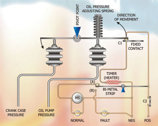
figure 1
1. The ability to subtract the crankcase pressure from the oil pressure and to measure this difference
2. Since at start-up there will not be a pressure difference between oil and crankcase, a timer must short-out (by-pass) the safety pressure switch for a predetermined time to enable the compressor to start and generate an oil pressure. If insufficient pressure is provided by the oil pump after the allotted time, the pressure switch must switch the compressor off
3. Ideally the oil safety switch will incorporate a warning light to show that it has tripped and a “normal” light to show correct operation
4. If the oil switch should trip-out due to insufficient oil pressure, it should not be able to reset itself automatically and therefore, a manual reset button must be incorporated.
Fig 1 shows how the above functions are achieved. The oil switch control has two pressure sensing bellows, one connected to a tapping on the compressor crankcase to measure vapour pressure, and the other bellow is connected to a tapping on the oil pump which is subject to the oil discharge pressure. These two bellows are in equilibrium when the compressor is at rest and all internal pressures have equalised. The contacts C1 and (A) will be closed. When the compressor is required to run contact C2 closes.
When contact C2 closes, current flows through contact (C1) to the heater and (A) to the motor contactor solenoid MS. The “normal” indicator lamp will illuminate and the compressor will run. If the compressor oil pump works correctly, the pressure in the oil side bellows will build up, exceeding the pressure in the crankcase bellows plus the pressure exerted by the oil pressure adjusting spring, and contact C1 will open, de-energising the timer heater.
If the oil pressure fails to reach the required pressure, contact C1 remains closed and the heater continues to heat the bi-metal strip which has been selected to bend after 120 seconds (in some cases 90 seconds) at which point the bi-metal strip bends and breaks contact (A) and makes contact (B).
The compressor will stop, the “normal” lamp will go out and the “fault” lamp will illuminate. In order to reset the switch, the manual reset button would force the bi-metal contact back to (A).
If during the run cycle oil pressure should fall, then contact C1 will re-make and the heater will be energised. After the predetermined time, 120 or 90 seconds, the bi-metal strip will open contact (A) unless, of course, oil pressure is re-instated within this time. This method of control protects against transient faults which may temporarily reduce oil pressure.
When fitting an oil differential pressure switch, ensure that the switch is located above the oil level of the compressor since this prevents oil migrating into the vapour bellows and interfering with the operation of the switch.
As in all methods of control, electronic control can replace the common electro-mechanical controller and extend the range of protection given to a compressor. Electronic controllers can measure the viscosity of the oil being fed to the compressor and if the oil contains excessive quantities of refrigerant, the compressor can be switched off. These controllers can:
1. Keep a record of the number of times the oil differential pressure switch fails to reach pre-determined set points
2. Measure oil temperature and either warn or switch off the compressor if the oil temperature is too high
3. Measure the pressure drop across the oil pump filter and give warning when this pressure drop starts to rise.
A good general rule is: The larger your compressor or the more critical your application, the greater the sophistication of your compressor protection.
Pump down control
Pump down is a useful method of control which reduces the risk of liquid refrigerant flooding within the compressor on start-up. This excess liquid can cause foaming of the oil, which reduces its viscosity and lubrication qualities. It can enter the cylinders resulting in damage to bearings and valve plates due to hydraulic compression.
Liquid flood-back can occur for the following reasons:
• Excessive amounts of liquid entering the evaporator during the off cycle whilst the compressor is at rest due to lack of cooling demand
• As a result of the thermostatic expansion valve phial being un-insulated and being warmed by ambient air
• The TEV valve seat failing to close fully.
As a consequence, when the compressor starts, a rush of liquid refrigerant (usually referred to as a slug) flows down the suction line and enters the compressor.
With pump down control, when the required setpoint temperature is reached, the system controller, usually a thermostat, will de-energise a solenoid shut-off valve located in the liquid line (liquid line solenoid valve). This valve will close and since no more refrigerant can enter the evaporator, the compressor will continue to draw superheated vapour from the evaporator thus emptying the evaporator. This in turn results in a progressive fall in the suction pressure as a result of the diminishing amount of vapour available at the compressor inlet. A low pressure switch will then switch off the compressor when the cut-out setpoint is reached.
When the temperature in the conditioned space rises above the setpoint of the thermostat, the liquid line solenoid valve is energised and the valve opens. Refrigerant passes into the evaporator and the suction pressure rises in accordance with the saturation temperature of the refrigerant within the system. When the pressure exceeds the low pressure switch setting (plus differential), the switch closes contacts and starts the compressor.
Since there is no excess refrigerant in the evaporator, (as can be the case on systems without a pump-down facility), the compressor experiences a greater degree of protection by starting in a relatively unloaded condition and without the possibility of liquid slugging. In order to reduce the flow of refrigerant into the evaporator after the liquid line solenoid valve closes, it is advisable to fit the valve as close as is practical to the expansion valve.
If the solenoid valve is fitted close to the condenser/receiver on a system with a long liquid line, the pump-down sequence can be protracted and may even result in a number of short cycles under the control of the low-pressure switch.
Some thought must be given to the low pressure switch settings. It is not uncommon for the service engineer to set the safety low pressure switch to cut-out at 0.136bar (2psig) on the basis that the system will be protected from running into vacuum conditions in the event of a leak. However a typical air conditioning system evaporates at 5°C. If the refrigerant in the system is R22, this equates to a saturated pressure of 5bar (69psig). Therefore, in order to cut-out on the low pressure switch, the saturation temperature will be the equivalent of -38°C when the pressure falls to 0.136bar (2psig). This sudden reduction in pressure to 0.136bar (2psig) on a system which has been running at a balanced condition of 5bar (69psig) causes the refrigerant mixed within the crankcase oil to evaporate which subsequently leads to oil foaming. Foaming oil is not a very good lubricant and is also easily pumped out of the compressor.
Therefore when setting the low pressure switch on a pump down system, the cut-out point should really be set at 0.2-0.27bar (3-4psig) lower than the normal operating pressure. However, one must not forget the conditions that may exist if capacity control is incorporated. Although we have referred to low pressure switches (LPS) and thermostats, we have not yet covered the construction details.
An LPS is connected by a capillary line or a small bore tube copper tube to the low pressure suction side of a compressor. The suction pressure passes through the connecting tube into a bellows assembly which expands as the pressure increases and contracts as the pressure falls.
The movement of the bellows acts upon a pivoting lever which incorporates a snap action, controlled by a spring. Most LPS are fitted with a single pole, double-throw switch mechanism and can be wired so that they can electrically make or break on fall of pressure.
The most common arrangement is for the switch to break contact on fall of pressure and the opening point is called the cut-out point. The cut-in point or contact-make point, is determined by the differential pressure setting. The typical range of cut-out pressures is between 0.5bar(a) and 8.0 bar(a). The differential pressure range is between 0.3bar and 4bar.
To set an LPS to cut-out at say 4bar and in at 4.75bar, identify the range adjusting screw and wind the screw until the pointer indicates 4bar (this is an approximation only), pressurise the switch (with dry nitrogen) until the contact makes. Then bleed the pressure slowly and read the pressure level at which contact breaks. Adjust the switch accordingly and repeat the operation until the switch consistently breaks at the required pressure. Now identify the differential adjusting screw and adjust the pointer to 0.75bar (Fig 2).
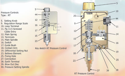
figure 2
Reduce the pressure until the switch breaks then gradually bleed the pressure into the switch and note the pressure at which the contacts make. Adjust the differential accordingly and repeat the procedure until the switch operates consistently at the desired pressure.
It is essential that the cut out pressure is set correctly first, followed by the differential pressure. LPS cut-out and differential scales are always marked on the switch. LPS are available with auto-reset or manual reset. They can also be supplied with integral indicator lamps to show when the contacts are closed and we advocate their use as a time-saving device when undertaking diagnostic work on systems.
High pressure switches
High pressure switches (HPS) are in every way identical with LPS in terms of construction and appearance, the only difference being the rating of the bellows assembly. The HPS is fitted with single-pole double-throw switches and can be wired to make or break on rise of pressure. HPS are available in ranges between 3bar and 30bar, with differential pressure setting ranges between 2.1bar and 8bar. When setting an HPS, set the opening pressure by adjusting the range screw, then set the closing pressure by adjusting differential screw. In order to achieve the high pressures required for testing the cut-out and differential settings, it is essential that dry nitrogen is used and a pressure-reducing valve as opposed to blocking the condenser coil airflow which could lead to system damage or pipework fracture and subsequent injury. The practice of closing the discharge valve while the compressor is running to pressurise the HPS is dangerous and must not be attempted.
Thermostats
Thermostats include: electronic; electro-mechanical; fluid sensing; air sensing; and surface contact sensing. The electro-mechanical thermostat operates in a similar manner to pressure switches but instead of being connected to a remote pressure source, the thermostat bellows is connected to a sealed phial containing a small liquid charge of refrigerant similar to thermostatic expansion valves covered earlier in the series. The pressure exerted by this refrigerant increases with a rise of temperature and decreases with a fall of temperature in accordance with the saturation temperature-pressure relationship. Accordingly, the bellows activates a switch mechanism resulting in make of electrical contact on rise of temperature starting a cooling cycle or make on fall of temperature, initiating a heating cycle.
The thermostat is set up in a similar manner to a pressure switch. If the switch makes on rise of temperature, the range screw is adjusted until the pointer shows the cut-in temperature and the cut out temperature is set by the differential screw. Conversely, if the thermostat makes on fall of temperature, the cut-in point is set by the range screw and the cut-out point is controlled by the differential adjustment.
Attention should be paid to the location of a thermostat or, more importantly, the thermostat sensing phial. The sensor should always be positioned so that it is subject to air movement and should not be located in a pocket of still, dormant air. Ideally the sensor will be located in the return airstream to the evaporator where it will read the current temperature of the air in the conditioned space or system. On close-control systems where temperature recorders are fitted, the thermostat sensor should be located immediately adjacent to the recorder sensor to avoid misleading readings of true conditions.
Conversely, it is unreasonable to measure the temperature in a room by randomly locating a thermometer or recorder without any reference to the temperature controlling sensor.
An important consideration is the temperature gradient that exists in all conditioned spaces. The temperature controller can only measure the local conditions immediately surrounding it. (Figure 3)
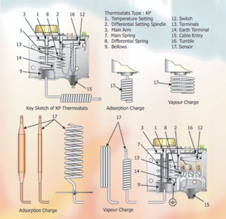
Figure 3
Temperature gradient
The temperature gradient is the difference between air at the inlet diffuser discharging air into a room and the temperature of the air leaving the room at the return air grilles. This gradient is a function of the gains/losses in a room and the airflow rate/number of air changes/h of conditioned air. Close control systems will have a high number of air changes/h while comfort conditioned rooms should be significantly less.
With thanks to Mike Creamer of Business Edge who revisits his Masterclass series of articles, updating and adding to the information which proved so useful to readers when the series was first published over ten years ago. In this reincarnation, the series will cover both air conditioning and refrigeration and serve as an on-going source of technical reference for experienced personnel as well as providing a solid educational grounding for newcomers to our industry.