Mike Creamer of Business Edge revisits his Masterclass series of articles, updating and adding to the information which proved so useful to readers when the series was first published ten years ago. In this reincarnation, the series will cover both air conditioning and refrigeration and serve as an on-going source of technical reference for experienced personnel as well as providing a solid educational grounding for newcomers to our industry.
In order to overcome cyclic single compressor system limitations, a number of capacity control methods have been devised over the years and these have worked relatively successfully. However, there are disadvantages and limitations in some cases. These are broadly defined below.
Cylinder unloading
Where semi-hermetic or open-drive compressors are concerned it is possible to apply cylinder unloading in order to reduce the capacity of the compressor. This effectively disables the ability of certain cylinders to pump refrigerant, albeit power is still absorbed in moving the pistons up and down and as a result of frictional losses, etc. Hence, cylinder unloading has efficiency penalties.
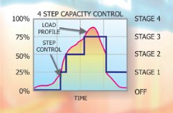
Fig 1: four-step capacity control
However, cylinder unloading has an added advantage in that it is possible to start the compressor in an 'unloaded' condition such that, for example, the motor has only the load of one piston out of four to overcome during the start-up phase. The remaining cylinders are progressively 'loaded' to meet the current capacity requirement.
Therefore, a four-cylinder compressor can provide four steps of capacity control: 0%, 25%, 50%, 75% and 100%.
Screw compressors are also fitted with an unloading capability, although this normally has the key advantage of being infinitely variable from 100% down to approximately 10% of the compressor capacity. Providing such an arrangement does not impose severe efficiency penalties, then this will be a very acceptable form of capacity control, theoretically achieving good energy savings and close temperature control within the conditioned areas.
However, it is certainly true to say that in the early days capacity control with screw compressors gave disastrous energy saving results.
For example, while the capacity of the compressor could be reduced from 100% to 10%, the power input might only fall to 50% or 60% of the full load energy consumption. Fortunately, things have improved substantially in this area, but care must be exercised in selection of such compressors to ensure they are suited to the application.
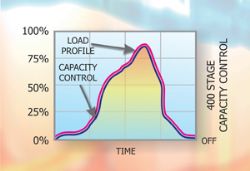
Fig 2: load profile of a continuous capacity control system
Multiple compressor systems
Improved capacity control can be achieved by arranging two or more compressors in parallel. Fitting one or more of these compressors with cylinder unloading, as described above, can bring about more unloading steps and finer control. Energy savings may be significantly improved.
Nothing consumes less energy than a compressor that isn't running. Multiple compressor systems therefore allow superior control and energy savings. The compressors can be sequenced differently to even-out wear. It is also possible to isolate individual compressors to allow service and repair work to be conducted, while the remainder of the system continues to run.
It is also possible to select multiple compressors of either equal capacity or to use compressors of dissimilar sizes, since this latter arrangement provides greater control flexibility and smaller incremental capacity steps.
Hot gas bypass
This comprises a special control valve that is normally reactive to system pressure changes as the load at the evaporator varies from full- to low-load conditions.
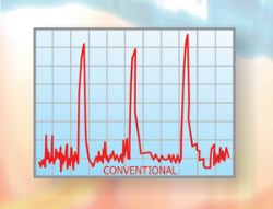
Fig 3: conventional frozen food temperature profile
The hot gas bypass valve allows a proportion of the discharge vapour leaving the compressor to enter the low pressure side of the system, thus providing a false heat load to keep the evaporator 'busy'.
This effectively reduces the system capacity, while keeping the compressor fully occupied by pumping a constant volume of vapour. This is hardly energy efficient, but it does provide good capacity control.
There are a variety of hot gas bypass methods but these will not be covered in technical detail at this point in time.
Suction pressure regulation
It is possible to use a special control valve that modulates the flow of refrigerant vapour into the compressor at the suction inlet. This must be used carefully in accordance with the type of compressor in order to avoid motor overheating and is not the method of control commonly used.
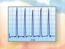
Fig 4: CVC Frozen food temperature profile
Continuously variable capacity (VRF)
This technique employs a power inverter to control the speed of the compressor motor and thereby vary the mass flow of refrigerant vapour through the compressor. Such control allows the air conditioning system to be varied infinitely in its capacity and, even though there may be minor losses (electrical inefficiency) through the inverter, the savings in refrigeration system energy can be very substantial indeed.
This technology can therefore provide absolutely superb temperature control in most applications.
A comparison of systems with steps of capacity control versus continuously variable capacity control is shown in figs 1 and 2.
As can be seen from fig 2, the system is able to perfectly match capacity to the load profile thus providing excellent temperature control and substantial energy savings.
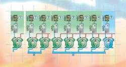
Fig 5: single and multiple VFD systems
Energy savings
Real case examples of energy savings, directly involving the author, were independently proven in trials with a leading supermarket refrigeration chain here in the UK.
Using very sophisticated microprocessor controllers, reciprocating compressors were driven by power inverters and achieved the following results, these being independently monitored by a leading firm of UK consulting engineers.
Application - fresh meat
Design temperature 0°C.
Temperature control +/- 0.5K
Energy savings* 56%
Application - frozen food
Design temperature -21°C.
Temperature control +/- 0.5K
Energy savings* 29%
*When compared to the previously installed and carefully monitored fixed speed cyclic systems serving the same food display case loads.
Continuous variable capacity control
Continuously variable systems have numerous key advantages over cyclic systems and these include:
· Several hundred steps of capacity control.
· Substantial energy savings (29% - 55%).
· Substantial compressor motor protection.
· Soft start with low current in-rush.
· Ability to drive compressors at 60Hz (1800 rpm synchronous) on a 50 Hz (1500 rpm synchronous) power supply, thus providing more capacity for the same compressor size to meet peak loads.
· The ability to deal very effectively with systems of several evaporators. Indeed such systems could cope easily with 50 evaporators or more.
· The ability to respond very rapidly to changes in system load, brought about by either internal load changes or ambient temperature changes, or both.
· Extremely close temperature control.
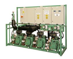
Fig 6: multiple compressor pack
Temperature control
The final objective of most refrigeration and air conditioning systems is to attain good temperature control in a conditioned space such as a cold room, a refrigerated display case or some other process cooling function. If this is the primary objective, then surely this is one of the most important elements to consider.
Cyclic on/off systems with either a single step or several steps of capacity control can never match the cooling capacity precisely to the cooling load, since load is infinitely variable in most situations. A continuously variable capacity system with several hundred steps of capacity control will fit the refrigeration capacity far more precisely to the ever-varying load and precision temperature therefore results.
Fig 3 shows a typical temperature profile for a frozen food display case being served by a single stage, on/off condensing unit. The evaporating temperature is approximately -30ºC and the display case air temperature should be close to a set point ranging from -18ºC to -21ºC.
The higher peaks that can be seen in the graph are defrost intervals where the refrigeration is stopped, electric defrost heaters are energised and the air temperature is taken to +10ºC to ensure the complete dissipation of ice and residual water droplets from the evaporator coil. The refrigeration system then resumes operation and the display case temperature is progressively pulled down to around -18ºC/-21ºC.
A quick glance at the temperature control between the defrost intervals shows an unacceptably wide temperature swing.
It is also interesting to note that the rate of temperature pull-down following defrost declines as the temperature in the case is reduced, primarily due to the ever-reducing efficiency of the refrigeration system at lower operating temperatures.
Now compare the graph in fig 3 with that in fig 4: this system is served with a single variable speed compressor with a minimum speed capability of 450 rpm and a maximum speed of 1,800 rpm. Note the fine temperature control between the 4hr defrost intervals. It is also important to observe the vastly improved recovery time to the design temperature following defrost, this being much better than the cyclic system.
Given a conventional compressor running on a 50 Hz power supply can only attain a speed of 1,450 rpm (1,500 rpm synchronous), the compressor capacity is bound by this limitation (ignoring other system factors). When compressors can be driven to higher speeds for short periods, increased refrigerant mass flow for the same size of compressor is possible.
Overshooting the temperature target
A cyclic fixed speed system with simple temperature controls incorporating a differential of 2-3 K is forced to control the desired temperature within a 'band', the width of the band being determined by the temperature differential setting. This differential is absolutely essential on fixed speed on/off systems to avoid excessive cycling of the compressor, which would otherwise shorten its life.
Accordingly, if a temperature of -18ºC is required and the differential on the controlling thermostat is 3 K, it would be wise to ensure that the control set point is set such that the compressor comes on when the temperature rises to -18ºC and is switched off when the temperature reaches -21ºC, especially if the highest allowable temperature for the frozen food is -18ºC. However, when the system is operating beyond -18ºC, its efficiency, as with all refrigeration systems, is partially reduced and the power input is increased due to extended running time.
A continuously variable capacity system with the capability of matching its speed and capacity precisely to the load will not suffer from this problem since it will always maintain the set point temperature of -18ºC (within a fraction of a degree) and will therefore not suffer from overshooting the set point temperature. Efficiency is therefore maintained at the optimum level and power input, running cost and CO
2 emissions are then reduced.
A system with continuously variable capacity control can update its performance several times every second. Continual monitoring of air temperature, product temperature or chilled water temperature provides the necessary feedback to the control algorithm, which can then adjust the compressor speed instantaneously to the revised capacity requirement.
Single, multiple and satellite VRF
The key components of a continuously variable capacity refrigeration or air conditioning system are:
1) Microprocessor controller;
2) Power inverter (VFD - variable frequency drive);
3) A compressor specifically designed for variable speed applications;
4) A special expansion device.
These four basic components or multiples of them, can be arranged in many combinations to suit a wide range of applications and several examples are illustrated in fig 5. The variations shown include single and multiple compressor systems.
The system showing five compressors comprises two refrigeration circuits serving several evaporators each (compressors 1/2 and 3/4). In addition, compressor five is serving a single evaporator running at an entirely different temperature to the other evaporator groups on the system.
This five-compressor system has a single refrigeration circuit and all three groups are sharing the same condenser/receiver set-up.
Fig 6 shows a multiple compressor pack system similar to the five-compressor system shown in fig 5.
In this example, there are four compressors of equal size. Power inverters could be used to independently control each compressor, yet all could share the same refrigeration circuit.
These arrangements allow individual compressors to serve a single evaporator at a different set point temperature to other evaporators on the system. A pair of compressors could serve one or more evaporators and can be run singly or as a pair to suit the load. Indeed, almost any variation is possible.
Oil level controls
The refrigeration compressor pack in fig 6 shows oil level controls fitted to each of the compressors.
The large single multi-fan condenser serving this refrigeration compressor pack will be allowed to run at full capacity until the condensing temperature falls to around 10ºC. This is a phenomenal method of reducing energy consumption, given that most systems hold the condensing temperature at rather high levels (45ºC, for example). This subject will be covered later.