Unit selection
Firstly, we need to calculate the peak heat gain for each office or room including the fresh air load. It is recommended that one does not over-estimate as it is better that a compressor runs for longer periods rather than frequent on-off cycling which occurs when a unit has excess capacity. Such excess capacity may also result in large swings of temperature from hot to cold.
We then need to consider which method of heat rejection is to be used, ie dry air cooler, evaporative cooling tower, etc. This will determine the system water loop temperature and permit simple selection of the most suitable units based on their performance at the rated water temperature (see fig 1).
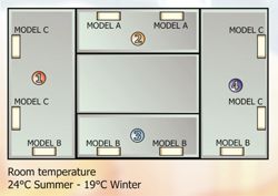
Fig 1: Floor plan
On occasions it of course becomes necessary to reject heat. Rejection may be by a dry cooler or an evaporative closed circuit cooling tower or an open type in conjunction with a plate heat exchanger. Heat rejection may also be via a thermal storage system, heat pump or ground source.
In all cases, contamination of the system water must be avoided and under no circumstances should cooling water be used directly in the reverse cycle heat pump units. With minimal approach temperatures, ie water off the cooler at 3K above ambient, machinery tends to be larger and more costly, but gives greater system efficiency. Large approach temperatures allow for economical selection of dry coolers.
Whatever heat rejection system is used, the reverse cycle heat pump systems leaving water temperature should not be designed to drop below the continuous operating range limit. It is also important that cooling towers and dry coolers are provided with frost protection during the winter months, sump heating may be necessary on cooling towers.
Draining down is not recommended as a method of frost protection as some cooling may be required in cold weather. An automatic three-way valve with bypass is commonly used, arranged in such a way to bleed adequate water through the cooler coil thereby preventing freezing, as well as bypassing the rest of the system to keep minimal heat loss from the cooler coil when no cooling is required. It is important that the manufacturer of the equipment is consulted on this point.
The following example covers the calculation steps necessary for the selection of a dry cooler.
qc = unit total cooling output (kW)
qe = unit electric input (cooling kW)
Qc = peak building load (kW)
v = unit water flow rate, l/ sec (kg/s)
dt1 = temp rise (°C), all units working
dt2 = temp rise (°C), allowing for diversity for excess unit capacity
4.187 = specific heat capacity (kJ/kgK of water)
dt1=(qc1+qc2 +qc3...)+(qe1+qe2+qe3...)
___________________________________
4.187 (v1+v2+v3...)
dt2 = dt1 x Qc
_______
(qc1 + qc2 +qc3...)
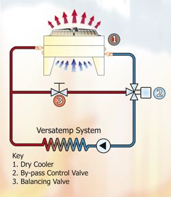
Fig 2
Temp of entering water = selected leaving temp (35°C) + dt2
Water quantity is the total pumped flow rate
(v1 + v2 + v3 ....)
Fig 3
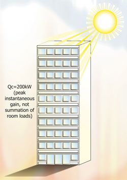
Fig 4
Model A 20 x 1.83kW = 36.6kW
Model B 40 x 2.27kW = 90.8kW
Model C 40 x 3.10kW = 124.0kW
_______
(qc1 + qc2 + qc3 ...) = 251.4kW
Model A 20 x 0.90kW = 18.0kW
Model B 40 x 1.11kW = 44.4kW
Model C 40 x 1.36kW = 54.4kW
_______
(qe1 + qe2 + qe3 ....) = 116.8kW
Model A 20 x 0.064 l/s = 1.28 l/s
Model B 40 x 0.075 l/s = 3.00 l/s
Model C 40 x 0.114 l/s = 4.56 l/s
________
(v1 + v2 + v3 ...) = 8.84 l/s
7.92°C x 8.84 x 4.187 = 293.1kW
35°C + 7.92 = 42.92°C
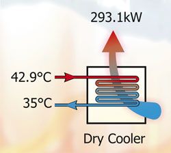
Fig 5
Heat injunction
There is a need for heat injection prior to commencement of the starting sequence of the Versatemp reverse cycle heat pump system and for occasions when sufficient heat is not being recovered in the building. Typically, low-pressure hot water systems with modular boiler operating at say 82° to 71°C for indirect heat injection would be ideally suited.
As with any other closed water system there must be provision to ensure the water cleanliness and safety controls applied to prevent overheating or excess pressures. The peak building heating load should allow for diversity of heat loads and include fresh air unless full pre-heating to room temperature is carried out by other means.
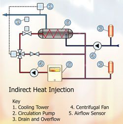
Fig 6
It should be noted that the total heat injection method employed should take into consideration any pre-heat of the fresh air ventilation plant, together with any other heating services that are to be provided. As well as the Versatemp System load, selection of the plant to meet the system heating needs is dealt with in a similar manner to cooling, excepting that the kW input is subtracted from, instead of added to, the unit capacity, as follows (the following example covers the calculation necessary for the selection of the heat exchanger, NOT the boiler or prime heat source):
qh = unit heating output, kW
qe = unit electric input (heating) kW
v = unit water flow rate, litres/s (kg/s)
Qh = peak building heating load, kW
dt3 = temp drop °C, all units working
dt4 = temperature drop °C, allowing for diversity for excess unit capacity
4.187 = specific heat capacity, kj/kgK of water
dt3 = (qh1 + qh2 + qh3...) - (qe1 + qe2 + qe3 ...)
__________________________________
4.187 (v1 + v2 + v3 ...)
Qh
dt4 = dt3 x __________________
(qh1 + qh2 + qh3 ....)
kW x 860 = kcal/h l/s x 13.2 = 1 gpm
The above calculation covers steady state conditions, and due allowance should be made on a boiler/heat exchanger margin for early morning starts.
Model A 20 x 3107kW = 61.4kW
Model B 40 x 4130kW = 172.0kW
Model C 40 x 4160kW = 184.0kW
__________
(qh1 + qh2 + qh3 ...) = 417.4kW
Model A 20 x 0.78kW = 15.6kW
Model B 40 x 1.10kW = 44.0kW
Model C 40 x 1.20kW = 48.0kW
__________
(qe1 + qe2 + qe3 ....) = 107.6W
Model A 20 x 0.064 l/s = 1.28 l/s
Model B 40 x 0.075 l/s = 3.00 l/s
Model C 40 x 0.114 l/s = 4.56 l/s
_________
(v1 + v2 + v3 ...) = 8.84 l/s
dt3 = 417.4 - 107.6 = 8.37°C
___________
8.84 x 4.187
dt4 = 8.37 x 180 = 3.6°C
___________
417.4
3.6°C x 8.84 x 4.187 = 133kW
35°C - 3.6°C = 31.4°C
Water system
The water circuit should consist of a two pipe closed system, preferably reverse return, to facilitate a balanced flow to all units. In large systems, temperature and pressure test points at main branches are advisable to permit an accurate check on local conditions within the system. Balancing valves should also be provided at all main branches to facilitate the water balancing of the system and guarantee adequate water flow to every reverse cycle heat pump. The unit water connection should comprise the reverse cycle heat pump flexible hoses, flow regulator and isolating valves.
The piping system should be sized on the sum of units' flow rates. It is important to remember that all reverse cycle water source heat pump units should receive the specified water flow rate at all times. Therefore the pump duty is the sum of flow rates of all units supplied. It should be noted that some recent systems operate on inverter driven pumps, where individual terminal units shut off the flow when in the dead band or off cycle. This can offer significant energy savings.
The water pipe work materials may be black mild steel, copper, plastic or stainless steel (but not galvanized) appropriate to the temperature and pressure conditions. The reverse cycle heat pump unit water coils do not incorporate air venting cocks, this is because the water velocity at the specified flow rate is sufficient to carry air into the piping system, where provision must be made for venting. Where a unit is at the top of rising pipe connections, air vents should be fitted close to the unit, because the pump differential may not be sufficient to push the air down into the return main.
Water system temperature control
A water temperature between 20° and 43°C is required at entry for reverse cycle heat pump units. The optimum temperature will depend on the climate and costs of energy. Lower temperatures within the range mean better efficiency on cooling and higher temperatures are better for heating.
For typical temperate climates a temperature of 35°C is the minimum readily attainable by the dry cooler at maximum design dry bulb temperature. Therefore this temperature is considered the safest on which to select the units for satisfying design-cooling load, and to select the dry cooler.
However, it would be beneficial to have a water temperature set point of about 33°C with a differential of ±2°C, especially in buildings with year round internal heat gains, which is increasingly the case. At this lower setting the dry cooler would work longer but this extra cost would usually be more than offset by the reduced power input to units on cooling. The water temperature would rise to about 35°C during high ambient dry bulb conditions, when the dry cooler could not attain 33°C leaving water temperature.
System interlocking and control
1. Thermostat Tw1 modulates the cooling and heating valves Vw1 and Vw2 in sequence to hold a flow temperature at the required set point.
2. Thermostat Tw2 is a low limit control to switch off the electrical supply to the reverse cycle heat pump air conditioners, should the supply water temperature fall to 18°C and restore supply on a rise to 22°C.
3. Tw3 is a high limit thermostat to switch off the electrical supply to the reverse cycle heat pump air conditioners, should the supply water temperature rise to 45°C and restore supply on a fall to 41°C.
4. A flow switch will switch off the electrical supply to the reverse cycle heat pump air conditioners should the water flow fall to 75% of the rated flow.
5. Vw1 and Vw2 by-pass when the reverse cycle heat pump system water loop is within the heat balance limits. When supplementary heating is required Vw2 will modulate to permit water flow through the supplementary heat source. Similarly a requirement for heat rejection will modulate Vw1.
6. A thermostat TW4 is recommended in the return pipe of the water loop circuit. On achieving the minimum return temperature 20°C the units can be enabled and thermostat TW4 switched out of the circuit.
Safety devices
These are normally located in series with the time switch controlling the reverse cycle heat pump units. The safety devices recommended are:
(a) High limit thermostat, TW3 should be mounted in the flow pipe to the units to cut off the electrical supply.
(b) Lower limit thermostat, Tw2 should be positioned beside the high limit thermostat, to cut off the unit electrical supply, should water temperature fall below the specified limit. This should automatically restore supply on rise of temperature.
(c) A flow switch, located after the strainer, is required to cut off the electrical supply to all units, should the flow rate drop below 75% of the design rate. This should automatically restore the supply when the normal flow rate is restored.
(d) Frost protection of the heat rejecter must be incorporated. This could take the form of an outside ambient thermostat overriding all controls to operate Vw1 to the rejecter, to by-pass enough water through the rejecter to prevent freezing. Any exposed unprotected pipework must be trace heated separately.
(e) Frost protection should be provided in buildings to prevent condensation and freezing whilst unoccupied. In reverse cycle heat pump systems the electrical maximum demand can be more easily reduced if the room temperature is kept to a minimum of say 10°C. The boiler and pumps should be operative at all times to maintain a minimum water temperature of 5° - 10°C, unless a glycol mixture is used.
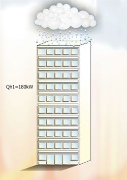
Fig 7
With thanks to Mike Creamer of Business Edge who revisits his Masterclass series of articles, updating and adding to the information which proved so useful to readers when the series was first published over ten years ago. In this reincarnation, the series will cover both air conditioning and refrigeration and serve as an on-going source of technical reference for experienced personnel as well as providing a solid educational grounding for newcomers to our industry.