FAN coils represent something of a paradox in the hvac equipment market. Compared with some other types of equipment, fan coils, in mechanical terms, are relatively unsophisticated. Yet they can offer a range of performance and siting options which can be tailored to suit innumerable applications.
FCUs are available in two main categories depending on control methods. The more traditional type is via waterside control valves that regulate the heating and cooling output by varying the low pressure hot water/chilled water flow rate through the appropriate coil. This is the four-pipe configuration, generally considered to be the best with the simplest form of operation. Options involving two-pipe cooling only, in certain instances, coupled with some form of auxiliary heater such as electric resistance, have their place when necessary.
Airside control units, regulate the units' output by adjusting the amount of air passing over the cooling or heating coil, or by-passing both coils if no treatment is required.
Low pressure hot water (LPHW)/chilled water will pass through the heat exchanger coil unchanged when airflow over the coil ceases. There is therefore no need to modulate or shut off water flow on airside controlled fan coil units.
In this article we seek to 'lift the lid' on the humble waterside FCU and illustrate the uses and versatility of this type of terminal equipment.
As with all equipment, the constraints arise from physical size, capacity required, acoustic criteria and cost. Selection of units is generally made on the nominal cooling capacity at a medium fan speed setting. This should ensure that the unit is capable of meeting the conditioned space requirements for load/temperature control quietly, while offering a measure of capacity control flexibility should this prove to be necessary.
Waterside control FCUs consist of the following key components: chassis, insulation, fan(s), coil(s), controls, air filter(s) and air distribution facilities.
Chassis construction depends on the size and configuration of the key components, but units can be as slim as 120mm and thereafter in all manner of shapes and sizes to suit location. For example, they may be sited within a ceiling void, under a windowsill, within a wall space or behind a custom architectural enclosure.
Insulation material plays a key role in two principal areas of fan coil operation. First, it obviously provides a measure of thermal insulation to help maximise the effect of the cooling and heating air used to treat the space. However, of equal, if not greater significance nowadays, is the secondary aspect of its acoustic attenuation properties.
Visually, the cooling/heating coils employed in fan coil units are typically standard air-to-water heat exchangers employing copper tube and aluminium finning material. However, variations in output performance are made by selecting coils based on length, number of rows and tubes, circuitry and routing, fins per inch and fin style. Further variations can be achieved via changes in the supply of either air and/or water services through temperature or flow rate adjustments.
The capacity of the fan coil unit can be controlled by varying the water flow rate or changing the air flow rate through the respective heat exchangers (or a mixture of both).
Thus the controls could take the form of three-speed and 'off' fan control switch coupled with a basic on/off thermostat arrangement in the space being controlled. Alternatively, programmable electronic controllers could be used, capable of integration into a BMS operating with occupancy sensor inputs from doors and windows.
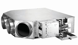
Sapphire fan coil unit from Quartz showing fan coils
Air filtration is a key aspect of all fan coil equipment. It should reduce the airborne contaminants while protecting the fan, motor and coil assembly from clogging. Depending on the particular application, a washable or disposable filter located upstream of the fan should prevent clogging of internal components.
Applications involving domestic dwellings, hotels and hospitals will require more frequent attention owing to the amount of lint present.
Air distribution options and unit configuration allow fan coils to be used throughout an installation, regardless of the variations in internal space requirements. The units can be vertical or horizontal, could be in the space mounted with a casing or enclosure, or remotely located with ductwork to/from the space being treated. The number of the ductwork connections can be varied as necessary.
Other aspects to be considered include provision of fresh air services to terminal units and condensate removal during the units' cooling operation.
Typical fan coil cooling and/or heating systems require an appropriate chiller, (or multiple chillers), boiler and circulating equipment, though advances in heat pump technology enable single-pack machinery to provide heating and cooling services.
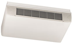
A cased fan coil unit
The key to system design is taking all possible steps to ensure that the operating specification is met, with no adverse noises when the units are running. Also important are proper installation and commissioning coupled with regular service and maintenance. Access for maintenance should be at the forefront of both the unit and site design.
End-user application for fan coils include government buildings, retail outlets, commercial office blocks, hospitals, hotels and financial dealing rooms and trading outlets.
A chilled water/LPHW fan coil system requires less building space than that of a fully ducted installation (pipework versus ductwork). It also benefits from the advantages of a centralised chiller and boiler plant while retaining the flexibility of local units being shut down in unused areas.
Units can be specific to areas or zones and so deal more accurately with their needs. Fan coils are also particularly suited to refurbishment and installation in existing buildings where the fitting of an air/ductwork system would prove difficult. The disadvantages of the fan coil relates mainly to maintenance, most of which has to be carried out in occupied areas, and the cleanliness of drain trays air filters, which has to be closely controlled.
Installation
Fan coil units provide an effective solution to cooling of multiple room buildings. There are also larger capacity, industrial fan coil units that are used, for example, in factory production areas. These are usually more rugged and do not offer the option of attractive casing and have a higher capacity than the FCUs used for comfort ac. The first step in selecting FCUs for an ac system is to determine the cooling and heating loads for each of the room(s) to be served.
The heat gains must be conducted using high accuracy calculation methods since under-sizing of the FCU will result in the room design condition not being attained under maximum summer ambient conditions and minimum winter ambient temperatures when heating is required.
Over-sizing, either by incorrect calculations or deliberately, to be 'on the safe side', is also undesirable since this will lead to unnecessary expenditure on not only the FCUs, but also the associated pipework, pumps and control valves and probably the central station chiller(s). Temperature control within the conditioned area may also be erratic. Costly mistakes can be avoided by conducting heat gain and loss calculations.
Having completed the heat gain and heat loss calculations, the appropriate unit(s) of the correct capacity can be selected. The conditioned space can be served by one or more FCUs and the number of FCUs required will be based upon adequate air distribution to provide even temperature and comfort whilst avoiding dead zones. FCUs must also be located so as not to create uncomfortable draughts.
Having decided upon the size and number of FCUs, the absorbed fan power must be considered. The specified noise level and required thermal capacity will be used to determine the fan speed to be used since both increase as the fan speed is raised. Many FCUs are fitted with an auto-transformer which takes 240V AC mains supply and provides multiple tappings of different voltages to enable the fan to be run at, for example, six alternative speeds. This is also termed a multi-tapping transformer. Tappings 1 to 6 can then be used to govern the motor speed.
Absorbed fan power
The fan motor fitted to a specific FCU must be sized and rated (in kW or horsepower) to deal with the internal resistance of components (coils, filter, casing, etc). The fan motor will also have to handle the required external static pressure where the FCU has to supply air to flexible ductwork and distribution air diffusers for example.
However, at lower fan speeds, the internal and external resistance will fall and the actual power absorbed by the motor will reduce. The sensible heat energy released by the fan motor is a function of the absorbed power, not the stamped overall power rating of the motor.
Accordingly, the amount of heat energy released by the fan-motor assembly into the air stream (and consequently the room being conditioned) needs to be established and this figure must then be added to the sensible gains for the conditioned space. Alternatively, this heat energy can be deducted from the sensible cooling capacity of the FCU.
Another approach is to include an estimated allowance for fan motor heat gain in the original load calculations. In some cases, the FCU manufacturer will declare the net cooling performance at different fan speeds/external static pressures, having deducted the fan motor heat gain from the actual cooling coil performance.
The fan motor heat gain works to our advantage when the FCU is running in heating mode and there is no reason why this benefit should not be taken into account when selecting the appropriate FCU(s) for the application.
While calculating the cooling loads for the conditioned space, the sensible heat ratio of the room will have been established thus identifying the cooling characteristics of the room. With this information, the optimum coil selection can be specified which will result in minimum system operating costs. For example, if the cooling characteristics of a coil result in excessive moisture removal, it would then be necessary to run the humidifiers within the fresh air ahu constantly, with a severe penalty on operating costs and GWP. According to the type of humidifier, this may result in further sensible heat being added to the room.
Conversely, if moisture removal were inadequate, increased humidity within the room could make occupancy conditions unpleasant and may even cause damage to the fabric of the building. In order to reduce humidity levels, the central plant would have be able to operate in dehumidification mode. This would probably require a lowering of the temperature of the cooling medium in order to increase the rate of condensation from the cooling coils. Unnecessary dehumidification and humidifying represent excessive running costs.
FCUs can use either direct expansion (DX) coils (evaporators) or water-cooled coils (heat exchangers). Each FCU can be a part of a multiple FCU installation connected to central cooling plant. This could be a water chiller or a large DX system.
Each system type has its pros and cons which we endeavour to list below. The strength of each argument in the pros and cons list will, to a large extent, depend upon the level of expertise in each of the disciplines involved, together with the resources available within a company who plan to install the system.
The pros and cons of DX based systems
The primary advantage of the DX system is that it is thermodynamically more efficient than a chilled water system. This is essentially due to the absence of a refrigerant-to-water heat exchanger which experiences heat exchange losses and requires pumping energy for the water.
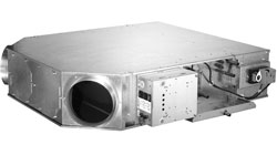
A chilled water fan coil
The heat exchanger and all the flow and return chilled water pipework, whilst insulated, also experience continual heat gain form the surroundings. DX system liquid refrigerant pipework requires no insulation, loses heat energy and actually benefits from this situation.
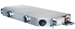
Slimline ducted fan coil
However, while this appears to offer a significant theoretical advantage over the chilled water system, in practice, the advantage is reduced by virtue of the greater heat exchange efficiency achieved by using all the heat exchanger internal surface area on water cooled FCUs.
Whereas the need for a DX system to use a thermostatic expansion valve requires between 4°K and 6°K of superheat to be generated within the evaporator resulting in only 80% of the internal surface of the evaporator being used efficiently.
An advantage of the DX fan coil however lies in the requirement for a smaller cooling coil (say one row). This is due to the cooling power of the evaporating refrigerant and the fact that the refrigerant evaporates at nearly a constant temperature throughout the coil leading to a large TD (temperature difference) between the entering air and the coil surface. Chilled water however may require three cooling rows, since the water can rise in temperature by only a few degrees (5 - 7 K) and in so doing, reduces the overall TD between the air and the coil surface temperature.
A greater mass of water is also required for the same cooling heat exchange than that required by refrigerant.
The capital outlay for a DX multiple FCU system is usually less than a FCU system that uses chilled water, particularly when a small number of FCUs are required. For a small system of up to three FCUs for example, chilled water systems are very rarely viable.
The forms of heating available on DX based FCUs are the same as on water-cooled systems. Both systems can use electrical resistance heaters or low pressure hot water (LPHW) heating coils. However, the DX system has a major advantage in that it can also use reverse cycle mode (heat pump). This mode of operation does not necessitate any additional pipework although the controls will be more complex. There are, of course, reverse cycle heat pump water chillers which can bring major heating efficiency advantages to water based systems.
Dehumidification is more easily built into a DX system. Often, all that is required is either a dual function suction pressure regulator or a by-pass around a single function suction pressure regulator allowing the system to reduce the evaporation temperature by a couple of degrees.
The cons
A significant detractor for using DX FCUs is the potential for refrigerant leakage and the larger the system and number of joints, the greater the potential. This potential for leakage requires greater levels of skill in piping the system due to the greater pressures within DX systems and the fact that the refrigerant is very fine from a molecular viewpoint. The refrigerant is also in vapour form in a good part of the circuit and can easily leak from defective joints in these regions. The ability to find leaks is significantly reduced if the FCUs and pipework is concealed.
Most DX systems are not as flexible as water-cooled systems in terms of load variation or from the point of view of changing the locations of FCUs. This is due to pipe sizing considerations, oil return and system load balancing. There are sophisticated, multi-split DX-based systems available which address these problems adequately, albeit at a cost. These will be covered in great detail in a later Masterclass.
On small to medium size installations, load variations between FCUs can be difficult to accommodate due to the need to match compressor capacity to evaporator load. On small compressors, capacity control is very often achieved by discharge gas by-pass (hot gas by-pass) while on medium size installations, the steps of capacity control are likely to be 50% or 33% and may have to be augmented with discharge gas by-pass. Any system that utilises discharge gas by-pass on a frequent basis is inefficient and very costly to run.
Large systems comprising multiple compressors which incorporate cylinder unloading, can adjust their capacity to match load variations by a much greater range of capacity steps, possibly down to 6% of total plant capacity. However, even this range of capacity control may not be sufficient on a critical system application since 6% of plant capacity may be significantly greater than the capacity of one or more FCUs.
The pros and cons of water cooled systems
The pros: A major advantage of water-cooled FCUs is their flexibility in terms of layout and ease of relocation. This allows an office layout to be easily revised.
Each FCU can be individually controlled by its own return air thermostat and the resultant load variation can be easily matched without the need to resort to discharge gas by-pass as is required in the case of the DX approach.
On medium to large systems, two water circuits are used. The primary circuit is between the refrigerant to water heat exchanger (water chiller unit) and a weir-buffer tank, while the secondary circuit is between the buffer tank and FCUs. A degree of thermal inertia is conferred by the buffer tank which absorbs small fluctuations in the load from the FCUs and prevents short cycling of the central station water chiller(s) which is unsatisfactory for the operation of the central DX refrigeration plant.
Generally, a medium to large installation will be more reliable than a DX system. This is primarily due to the most vulnerable elements of the installation, (the refrigerant pipe work, components and joints) being limited to a packaged item of DX equipment, safely located in a central plant room. Leak checking, detection and repairs are also easily carried out and the original assembly will have been conducted at the manufacturer's plant under controlled conditions .
The cons
Chilled water FCUs are not economically viable on small applications. Apart from the extra cost of incorporating a water chiller with the refrigeration system, the efficiency losses represent a significantly greater percentage of the overall operating costs. The overall coefficient of system performance is less than a DX system due to the need for water pumps and the additional heat exchange losses. Greater plant-room space is required to accommodate water tanks, pumps and associated controls.
Although water leaks are more easily found than refrigerant leaks, the damages resulting from a water leak can be far greater since refrigerant simply evaporates without little trace. A serious refrigerant leak in liquid form would of course be physically dangerous to occupants nearby. A major refrigerant leak in vapour form which might allow the entire system refrigerant charge to escape into a single room whilst occupied must also be considered dangerous.
The capital cost for a chilled water FCU installation will be greater than a DX system. This is due to the additional components required such as water tanks, water pumps, water to refrigerant heat exchanger, larger pipe sizes together with the extra pipe insulation required, bearing in mind that both the flow and return chilled water pipework between FCUs and buffer tank have to be insulated.
The ability to provide dehumidification with chilled water FCUs is considerably more difficult and costly.
Business Edge would like to thank Tony Hammersley and Karen Hiscott of TEV Ltd for their help with this month's graphics.
With thanks to Mike Creamer of Business Edge who revisits his Masterclass series of articles, updating and adding to the information which proved so useful to readers when the series was first published over ten years ago. In this reincarnation, the series will cover both air conditioning and refrigeration and serve as an on-going source of technical reference for experienced personnel as well as providing a solid educational grounding for newcomers to our industry.