Air cooled condensersThese normally consist of a finned coil matrix with one or more fans to force ambient air over the coil. The heat rejection capacity of an air-cooled condenser is mainly determined by the temperature difference (TD) between the refrigerant condensing temperature and the ambient dry bulb temperature. The main purpose of the air-cooled condenser is to reject to atmosphere heat energy from two sources:1. Heat energy extracted by the evaporator(s) from the conditioned space (comprising the sensible and latent cooling loads)2. Heat energy added to the system by the compressor (heat of compression) The sum of these is termed the Total Heat of Rejection (THR).It should be remembered that many systems employ hermetic or semi-hermetic compressors where the compressor motor is contained within the compressor housing and that motor cooling is achieved by passing the cool refrigerant gas returning from the evaporator over the motor windings. As the motor is cooled, the heat energy is passed to the refrigerant vapour, which must be rejected at the condenser to atmosphere. Condensers are therefore slightly larger for hermetic/semi-hermetic systems than
Air cooled condensers
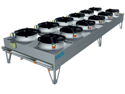
These normally consist of a finned coil matrix with one or more fans to force ambient air over the coil. The heat rejection capacity of an air-cooled condenser is mainly determined by the temperature difference (TD) between the refrigerant condensing temperature and the ambient dry bulb temperature. The main purpose of the air-cooled condenser is to reject to atmosphere heat energy from two sources:
1. Heat energy extracted by the evaporator(s) from the conditioned space (comprising the sensible and latent cooling loads)
2. Heat energy added to the system by the compressor (heat of compression) The sum of these is termed the Total Heat of Rejection (THR).
It should be remembered that many systems employ hermetic or semi-hermetic compressors where the compressor motor is contained within the compressor housing and that motor cooling is achieved by passing the cool refrigerant gas returning from the evaporator over the motor windings. As the motor is cooled, the heat energy is passed to the refrigerant vapour, which must be rejected at the condenser to atmosphere. Condensers are therefore slightly larger for hermetic/semi-hermetic systems than
Another interesting side effect in the case of hermetic/semi-hermetic compressors is that the heating of the refrigerant gas as it passes over the motor windings causes the specific volume of the gas to increase thereby resulting in a reduction of the mass of gas pumped by the compressor when compared to open-drive compressors. The compressor must raise the pressure and corresponding saturation temperature for the refrigerant above the maximum ambient temperature to allow heat energy to flow from the refrigerant to the relatively cool ambient air via the condenser. The superheated refrigerant vapour leaving the compressor undergoes the following changes as it passes through the condenser:
1. The refrigerant vapour dissipates sensible heat energy to the cooler ambient air and drops in temperature until the saturation temperature is reached. Only a small part of the condenser is required for this part of the process.
2. Once the saturation temperature is reached, the refrigerant starts to change phase (state) as latent heat energy is released. The largest part of the condenser is dedicated to this process since the majority of heat energy is released during this stage.
3. Liquid refrigerant at the base of the condenser will be at or close to the saturation temperature, which is still above the ambient temperature. Further sensible heat energy is then passed to the ambient air and the refrigerant is sub-cooled by a small amount. This sub-cooling is beneficial and only a small part of the condenser is dedicated to this. Systems with liquid receivers allow most of the liquid refrigerant to drain from the condenser and sub-cooling then occurs in the liquid receiver instead.
Condenser performance and capacity
The refrigerant condensing temperature is the saturated temperature corresponding to the pressure of the refrigerant entering the condenser and is therefore adversely affected by the pressure drop within the discharge line leading from the compressor. If a condenser is designed to operate at a 10K TD, a pressure drop in the discharge line equivalent to 1K drop in refrigerant saturation temperature will reduce the capacity of the condenser by 10%. Correct sizing of refrigerant lines is therefore essential and will be covered later in the series.
Assuming that the condenser has been selected correctly for the total heat rejection (THR) requirement and that the refrigerant lines have been correctly sized, the following points need careful consideration to ensure proper operation.
A. Draining of the refrigerant
One of the most common reasons preventing an air-cooled condenser from achieving its rated capacity is the failure of the condensed refrigerant liquid to drain freely. Refrigerant within the condenser is either a superheated or saturated vapour or a saturated liquid. Liquid refrigerant forms on the tube walls and passes through the coil and into the liquid drain line due to gravity. Inevitably, some refrigerant will still be in the gaseous state as it leaves the condenser although it will be just on the point of condensing into liquid. This gas must be able to leave the condenser or it will obstruct the free passage of the liquid – known as 'gas locking'. Gas locking will cause the condensing pressure to rise and the liquid line pressure to fall. This causes liquid to back up within the condenser and some of the condenser surface area provided to condense the refrigerant will become flooded by liquid and will no longer be available for condensation (latent heat rejection). With less surface available, the flow of refrigerant from the condenser will reduce whilst the compressor will continue to pump vapour to the condenser. The condensing pressure and saturation temperature will therefore rise thus increasing the operating temperature difference in an attempt to compensate for the reduction in surface area. The increase in the compressor discharge pressure also causes the power absorbed to rise. This will not only increase the system running cost but also cause the plant to shut down on high-pressure trip if either the load or the ambient are close to the design maximum.
The fall in the liquid pressure may reduce the amount of liquid passing into the evaporator depending on the type of control employed which would reduce the cooling capacity of the system. As these two effects tend to be linked, the system capacity will fall while the power absorbed will rise. Unfortunately things are never that simple and the reduction in liquid pressure and the rise in condensing pressure will vary as slugs of liquid manage to fight their way out of the condenser leading to system instability.
So what do we do to ensure that the condenser is adequately drained and gas locking does not occur? The secret lies in the sizing of the pipework leaving the condenser normally referred to as the 'condensate' or 'liquid drain' line. This line has to carry both the condensed liquid and any entrained gas. As gravity has a major influence in affecting refrigerant flow through this line, it must have a continuous downward slope over its entire length. In order to be able to handle both the condensed liquid and the entrained vapour the liquid drain line will need to be larger than the liquid line and should be sized for a maximum velocity of 0.5m/s (assuming the refrigerant is all liquid). This will allow the liquid to spiral down the tube walls and leave sufficient space for the gas to vent back into the outlet header of the condenser. If a receiver is being fitted below the condenser, the liquid drain line should be kept as short as possible, sloped as steeply as possible and have the minimum number of long radius bends. Elbows or short radius bends should not be used.
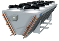
In many systems the receiver can be some distance from the condenser. In these circumstances the available pipe route is unlikely to be straightforward and it may not make economic sense either to run the large liquid drain line any further than necessary or to fit another receiver under the condenser. Arranging the liquid drain line to provide space for the liquid and gas to separate, by incorporating a large diameter section piped to provide a liquid seal, will be found to be adequate in most cases. A vertical separation vessel can be accommodated on condensers with horizontal coils within the height of the legs but the liquid drain outlet from units with vertical or 'vee' block coils will be close to the base of the unit dictating the use of a horizontal vessel. To be effective these must be of fairly large diameter.
NB: Every vessel must be designed such that it cannot fill completely with liquid and will be filled to maximum of 80% under the most adverse circumstances.
In some systems the condenser will incorporate a sub-cooling section either as part of the main coil or as an additional coil mounted in the air stream. The sub-cooling section will have been circuited to accept liquid and any gas present will cause liquid to back up into the condenser section. Sub-cooling sections must be piped via the liquid receiver or separation vessel in order to prevent this happening.
B. Siting
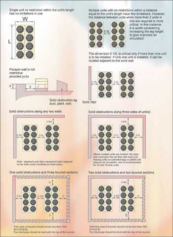
Air-cooled condensers are exactly what they say they are – air-cooled. If an air-cooled condenser is to operate successfully it is absolutely imperative that it receives the correct volume of air and at a temperature at or below the design ambient inlet temperature. The manufacturers' recommendations must be followed at all times if the system is to operate at design capacity, reasonable power input and for many years of trouble free operation. Compressor and motor life in particular will be extended if the correct guidelines are adhered to. Bear in mind that external air cooled condensers are designed to be installed in large open areas with no plant or walls close enough to affect or even restrict the air flow through the unit. Any item closer than approximately 2m and/or taller than the condenser is likely to have an adverse effect on performance.
Wind direction and the possibility of down draughts must be considered and units should not be sited in wells or be surrounded by two or more walls or equipment, which would create a similar situation. If an installation has to be screened, consideration must be given to the possibility of leaving the base of the screen open and the condensers should be mounted such that the fans are level with the top of the screen.
Localised air heating due to solar gain is very often experienced, particularly when condensers are installed on a roof with a highly reflective lightly coloured surface. Care in positioning and changing the roof surface treatment in the vicinity of the condensers will obviate the problem.
Recirculation (short cycling) of hot discharge air into the coil inlet face must be avoided at all costs. Low noise units tend to discharge air at around 15° to 25° above the horizontal making them particularly susceptible to recirculation. The aim is to have a large enough reservoir of air below the units to provide all the air required which can then be replaced without the velocity of the air entering the area having to exceed 1m/s. Under these conditions, sufficient air will be available below the units and recirculation would be unlikely. When several units are installed side by side, air blowing along the line of units can lead to hot discharge air from one unit being blown below the next downwind unit and so on. Where recirculation is a likelihood, consideration should be given to raising the units to provide say 2m between the plinth or roof slab and the coil inlet face. Where more than one unit is involved, mounting the units very close together will make recirculation more difficult. Multiple units mounted close together must be raised as discussed above.
Condensers with vertical coils (horizontal airflow) are more prone to recirculation and must be mounted in an open area. Again the manufacturers’ recommendations must be followed but usually an adjacent wall or other item is permissible at the air-on face provided it is approximately 1.5x the coil height from the unit. Vertical coil units are more susceptible to the effects of wind direction. When wind blows against the air flow direction, the overall capacity of the unit will be reduced while wind in the other direction may cause over condensing resulting in considerable drop in high side system pressure and a lack of control at times of low cooling load and/or low ambient.
This study of condensers continues next month.
With thanks to Mike Creamer of Business Edge who revisits his Masterclass series of articles, updating and adding to the information which proved so useful to readers when the series was first published over ten years ago. In this reincarnation, the series will cover both air conditioning and refrigeration and serve as an on-going source of technical reference for experienced personnel as well as providing a solid educational grounding for newcomers to our industry.