A chilled water distribution network is easily designed and there is no limit on the pipe run length or rise. Total life costs are affected by any changes to the system after installation. With higher churn rates compared to a few years ago, many organisations require a high-level flexibility in their buildings to adapt to changes of layout and staffing levels.
The two-storey Shaw Trust Employment Action Centre in Middlesbrough was the first building to use the chilled beam cassette. 
With chilled water it is relatively easy to add fan coils to the system and change the positions of existing units. Water based systems provide a high level of control of temperature as it is possible to modulate the output of each individual terminal unit, from 0% to 100%.
Chilled beam/ceiling systems that operate at higher water temperatures, not only have high chiller efficiency, but also make extensive use of free-cooling.
In some cases, a chilled water system may also be combined with thermal storage using the chiller to charge an ice or sub-zero store overnight to supplement the cooling in the day. The result is that the building operator can reduce the building's peak electrical load in addition to making maximum use of off-peak tariffs.
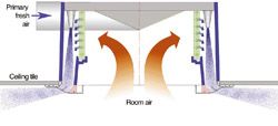
An airflow diagram of a chilled beam cassette
The fan coil
The modern fan coil comes in many sizes and versions, can have waterside or airside control, can accept any number of control options for factory fitting, can be standard depth or slimline, has nearly infinite variation on fan speed, is quiet, has been designed for ease of installation and use and is adapting to the Part L requirement by the use of DC motors.
The majority of fan coils used in the UK market are of the ceiling concealed type for connection to supply ducting. They are typically 270mm to 300mm deep and provide cooling duties at UK conditions from 1kW to 13kW with the added benefit of low noise levels. They are typically waterside control versions with the control packages being free issued for factory fitting.
Airside controlled units, while simpler to install, have historically suffered from heat pick-up from one coil to the other, resulting in poor energy efficiency. Modern designs have addressed this problem with the pick-up in dual-flow condition reduced below 5%.
Noise levels have also been addressed as have the problems of condensate leakage during high load conditions due to water carry over.
Motor design has also changed in recent times with external rotor motors almost standard nowadays. New developments in this field centre on the use of DC motors that have much higher efficiency than single phase AC motors.
The resultant energy saving, whilst appearing small on an individual unit, becomes significant on large jobs and will be a prerequisite of the design in order to comply with the requirements of the revised Part L of the building regulations.
Chilled Beams
Chilled beams and ceilings that are silent in operation and other energy efficient, environmentally attractive, air conditioning systems, are not a new phenomenon. In fact, over 2,000,000ft² of radiant chilled ceiling was installed in London's groundbreaking Shell Centre as long ago as 1961.
The number of installations has continued to grow over the years and the chilled beam market is now worth around £1.5m a year, according to BSRIA (The Building Services Research and Information Association).
Chilled beams and ceilings are continuing to gain acceptance among specifiers because, as well as their very efficient use of energy, they require little or no maintenance.
Preference for fan coils
According to a report carried out by the EC to encourage wider use of energy efficient systems, chilled beams and ceilings also provide high levels of comfort because of the very low air movement involved in their operation. The EC report on climatic ceilings and chilled beams points out that the UK is almost alone in northern Europe in continuing to prefer fan coils.
Minimal maintenance
Chilled beams have no moving parts so long life is guaranteed along with minimal maintenance - they deliver tampered, chilled air to the conditioned space without the need for a mechanical fan within the occupied area.
Being water-based, there is no refrigerant being piped around the building. A chilled beam system operates with a relatively high water temperature - typically 13°C or 14°C, and this allows cooling using natural cold water storage or free cooling from the outside air, for a large part of the year. The chiller will be needed only when the ambient temperature exceeds the chilled beam operating level and this high proportion of free-cooling dramatically increases the seasonal efficiency of the system.
Running expenses represent the majority of the life-time costs of a chiller, far outweighing the capital cost of the system and this will be accentuated as energy costs continue to rise. Due to this and initiatives such as the Climate Change Levy, end users are increasingly specifying the most energy-efficient plant available.
Free-cooling
To achieve these energy and cost savings, dedicated free cooling chillers that incorporate a free-cooling water coil next to the direct expansion cooling coil, have been developed. The chiller constantly monitors the external temperature and, once this falls below the temperature of the return water, free-cooling coils are brought into action to reduce the mechanical cooling requirement. The design also allows reduced capacity DX cooling to support the free cooling if free-cooling along cannot satisfy the requirement. In such a situation, the chiller is working in both mechanical and free-cooling mode.
In the UK for the six months of the year, from October to March, free cooling will provide most, if not all, of the cooling requirement and, even during the rest of the year, some free cooling will be achieved.
Condensation
Condensation problems with a number of chilled beam installations have restricted the take up of the technology. Previously the only way to overcome the condensate problem was to increase the water temperature but this had the undesirable effect of reducing the cooling load usually just when it was most needed.
Manufacturers have overcome this problem with a chilled beam cassette. These use an active chilled beam in the familiar form of an air conditioning cassette and, like a cassette, allows for condensate removal.
The first of this technology was developed in conjunction with Marstair and the Building Research Establishment at Garston, The Quartz - chilled beam cassette (CBC) combines the many benefits offered by active chilled beam technology with the cost and space saving advantages of cassettes. The CBC can also provide high or low temperature heating when fitted with one of the optional low pressure hot water (LPHW) coils. The unit has no moving parts and is low maintenance.
The CBC is one of the few active chilled beams with the facility for condensate collection and removal. This enables water temperatures (and hence cooling effect) to be maintained when the room conditions are such that condensate would be generated. Other chilled beams must stay 'dry' and do so by increasing the water temperature with a resultant drop in cooling duty.
The building fresh air supply is treated (filtered, then heated or cooled) in an external air-handling unit. This treated fresh (primary) air is introduced to the room via the chilled beam cassette, being discharged within the unit through specially designed nozzles located around the periphery between the coil and the chassis. The flow of air from these nozzles causes a negative pressure, thereby inducing a flow of air from the unit centre across the heat exchange coil(s). This air is replaced by warm air from the room that rises by convection and enters the cassette via the central grille.
The CBC is fitted with a coil optimised to suit the specific operating airflows and temperatures, a precision plenum chamber and nozzle arrangement and provides fourway discharge of the air.
The unit is available with various fascia options. The standard is fabricated from aluminium extrusions with a perforated centre panel and this can also be supplied with an integral light fitting if required. A plastic moulded cassette type fascia is also available.
Many modern builds have been designed to a sustainable agenda, incorporating high levels of thermal insulation and air tightness,
maximised daylight levels and passive solar gain control.
In order to cool the fresh air with the chilled water circuit without having a serious negative impact on both the chiller efficiency and the amount of free cooling, a compromise solution was reached. This involved operating the chiller circuit at a slightly lower temperature than the chilled beam circuit required and at a ?T of 5K as opposed to the beam circuit that operates at a ?T of 2K. The cooling coil in the air handler was sized such that, at design conditions, it would provide the required volume of fresh air at 14°C, using water at 11°C flow and 16°C return. The remaining chiller water was fed to a buffer tank, sized to ensure that no short cycling of the chiller occurred and that the AHU and beam circuit received the correct temperature water during a chiller off cycle.
The beam circuit was designed to operate at a flow temperature of 14°C with a return of 16°C. The flow temperature of 14°C was obtained by mixing, with a three-port valve, chiller water at 11°C and return water at 16°C. The beam circuit was provided with its own pump sized to provide the correct flow at the system pressure drop with a ?T of 2K.
Control
The main method of control for chilled beam cassettes is by modulation of the water valve but in this application several energy saving features have been incorporated.
The cassettes are grouped in zones with one valve controlling each zone. Whilst this control is totally adequate for zones that are fully occupied during the operational period, it is inadequate for zones, such as meeting rooms, that have intermittent occupancy. In such areas, control of both water and primary air is required.
When fully occupied, the control method is by modulation of the water flow as described above. When the occupancy level drops or disappears, the reduction in load causes the valve to close. The primary air however, being supplied at a low temperature, continues to cool the room. The controller recognises this and closes off the primary air supply to prevent over cooling the room. Closure of the damper creates an increase in duct static pressure, which is detected and, by means of a speed controller on the motor of the AHU, the overall fresh air supply is reduced.
The combination of sophisticated, energy efficient equipment coupled with partnering between the designers and suppliers at all stages of the project has resulted in the client obtaining a system that gives him the best of both worlds.
When using a chilled/LPHW water system it is easy to meet design loads, but determining the crossover point between heating and cooling for the first and last zones in the building requires effort, since the nett heating or cooling load for the other zones at these conditions must be determined. Generally, a software programme picks the information from standard sizing packages and calculates a unit selection list and their orientation in relation to the respective water circuits.
Examination of a typical spring/autumn day best illustrates the principle of operation of the system as it moves from pre-heat, simultaneous heat and cool, to full cooling.
The figures below show a stereotypical system with two air-to-water heat pumps, each with a two-pipe flow and return circuit (the minimum requirements, larger systems having multiple heat pumps on each circuit). Primary heat and primary cool are software labels, the primary heat unit will, in the event of any call for heating, provide hot water and the primary cool unit will, for any call for cooling, deliver chilled water.
Indoor unit coil sections are split for capacity steps of 70% and 30%. Connection of each coil section to the water circuits depends on zone load characteristics. The nature of the part load (the nett requirement in any zone X, when the first zone in the building changes from heat to cool) determines the orientation (30% to 70% to the primary cool) whilst the room load determines the unit selection.
Put simply - when the first zone in the building changes from heat to cool, if the load in any zone X is cooling, then the 70% coil section will be connected to the primary cool circuit and the 30% coil to the primary heat (and vice versa for heating). The size of the load determines the unit size, as the coil selection must be capable of meeting the part load on its own.
Initially, this is simple - all zones require heating; this is communicated to the central controller, which signals both outdoor units to operate in heating mode. 100% capacity is devoted to heating, how water is available in all four pipes, all valves are opened and 100% of each unit is used for heating.
Although water temperatures are around 40°C, using the full coil ensures heating duties are comparable to the units' cooling duties. With increasing occupancy and some solar gain, the heat requirements for the building plummet, and any zone may rapidly change from a heating to a cooling requirement. The cooling demand from this zone is communicated to the primary cool heat pump, which stops heating operation, reverses cycle and re-starts in cooling mode. All valves on the coil segments connected to this circuit are closed and the unit only cools the mains water, when the water temperature becomes suitable for cooling, the valve on the coil section (in the zone that requires cooling), that is connected to the primary cooling circuit) opens and the part coil cools the zone whilst all other zones continue to be heated by their part coil segments. These segments must be large enough to cater for the nett load (the difference between the heating and cooling) at this condition.
As the day progresses, more and more zones switch from a heating requirement to a cooling demand unit there is only one zone left with a small heating load. At the design stage this condition must be determined and hence the maximum part cooling load for the other zones to ensure that there is sufficient capacity in the part coil section to provide the room cool requirements. Finally, the last heating requirement signal will be lost and only cooling calls exist. Initially, the primary heat heat-pump stops and all valves connected to its circuit are closed. After a defined time lapse, when only cooling calls are received, the unit will re-start in cooling mode and the system will run up to design cooling, with 100% of outdoor and 100% of indoor capacity available to cool.
Body