Plant Room Dampers
Low ambient conditions are most severe on individual condensing units located externally and more difficult to overcome. However they also affect systems located in plant rooms and the design of the plant room must therefore take into consideration the effect of air entering at low temperature.
A typical arrangement is where the condenser is connected to a duct which discharges the warm air to the exterior of the building. Fresh air to replace the air discharged air enters the plant room through louvres or an intake duct. In a plant room with this configuration the effects of low ambient air can be countered by combining two pressure actuated dampers connected to the same discharge line but adjusting the linkage on one so that it closes on rise of pressure when the other opens. See Figure 1.
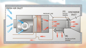
Figure 1: Controlled condenser air recirculation
When the plant starts and condensing pressure is low, damper (A) is closed and damper (B) is open. The condenser fan, which in this type of application runs at constant speed and provides air at constant volume, blows the air through the open damper (B) which then recirculates into the plant room. The air re-enters the condenser and the temperature is increased by heat from the discharge gas. This process continues and the temperature of the air entering the condenser continues to rise as will the discharge pressure, until the dampers are actuated. As the condensing pressure approaches design condition, the damper (A) will progressively open and damper (B) will close. This action will continue until the resultant mix temperature of recirculated air and incoming low ambient air reaches a balance close to the design condensing temperature.
Multiple Fan - Fan Cycling
Where a single fan is fitted to a small condenser, variable speed of the fan can be replaced with Fan Cycling. This single stage or step of control would result in a very crude means of capacity control since the system high side pressure would rapidly rise following shutdown of the fan motor and would quickly fall when the fan motor was re-started. The compressor would suffer adverse and unstable operating conditions and the effects at the evaporator would also be very erratic. Variable speed is therefore the most preferable means of control in this situation.
Larger systems with substantially greater heat of rejection obviously require condenser coils of greater surface area. In order to achieve reasonably even airflow over these larger coils, a number of axial flow fans are used. Use of several smaller fans also enables lower and more acceptable sound power levels to be achieved as opposed to using a single large fan.
The presence of a number of fans allows more flexibility in controlling the high side pressure for low ambient control purposes since several stages of airflow rate can be attained by simply switching one or more fan motors off. If 8 fans are present, these could be progressively switched off, one at a time, in response to falling high side condensing pressure. The effect of each fan on the system would not be dramatic, and reasonably stable operating conditions could therefore be maintained.
Multiple Fan Cycling can be achieved by means of Sequential Pressure Switch Operation which operates as follows:
Several HP Switches are connected to the high pressure circuit of the refrigeration system. Each is independently wired to a specific fan motor assembly. They are then carefully adjusted to slightly different pressure set points. As the high side system pressure falls in response to decreasing ambient temperature, the HP switch with the highest setpoint trips and shuts down one fan motor. This causes the system pressure to rise again. The pressure may rise to a point where the fan is restarted and this fan will continue to cycle on and off. The frequency of cycling will be purely dependant of the differential pressure setting of the HP switch.
If the ambient temperature falls a further small amount, this fan motor will remain off. Should the ambient temperature continue to fall, the second HP Switch with a slightly lower pressure setpoint will shut down a second fan motor assembly. The differential setting of all switches should be the same. These settings will of course vary according to the refrigerant type within the system and must be related to the desired range of control of saturation temperature.
While this system is mechanically simple and the components used are familiar to all Service Mechanics, a key shortfall in this approach is that of pressure switches falling out of calibration and the difficulty in setting these initially to a sufficiently accurate degree. Both these factors override the initial low capital cost of the components and result in a much more costly installation.
A microprocessor based controller utilising a pressure transducer could be used to solve the problem of drift of set points and differentials experienced with mechanical switches. If the pressure transducer were to go out of calibration, the relational settings would still remain the same.
Motorised Step Switch Control
An alternative to the above arrangement but which achieves the same results is to use a dead-band controller working in conjunction with a motorised multiple switch cam assembly. With this type of controller, the dead-band control device, can be either pressure or temperature sensing.
The controller contains a three position switch. When the pressure is at its set point the switch is at its centre position and in this position the switch is dead (the control circuit is open circuit). When the pressure rises, it passes through the predetermined dead band range and, as the name implies, nothing happens in this zone. As the pressure continues to rise, the switch changes over to its high pressure contact and passes a supply to the cam motor which causes it to rotate a central spindle. Fixed to the spindle are a number of adjustable cams and each cam is aligned with a switch contact. As the cams rotate, they force the switch contact to close at a predetermined angle of rotation.
Each switch is connected to a contactor which will energise a fan motor when the contact is closed. The more the spindle rotates the greater the number of switches closed. When the number of fans running matches the load on the condenser and the pressure starts to fall back to its set point, the dead band controller switch breaks the high pressure contact and reverts back to its centre (dead position). The cam spindle retains its current position and all the cam switches also remain in the condition they were at when the dead band controller opened the high pressure contact.
If the pressure starts to fall and goes below the dead band range, the dead band controller contact changes from its central position to its low pressure contact and energises the reversing circuit on the cam motor. As the spindle reverses rotation, the switches which had been closed by the cams are now opened and this operation continues until sufficient fans have been switched off to allow the condensing pressure to start to rise to the set point of the system at which time the dead band controller changes back to its centre, (dead) position.
The dead band control described above related to a pressure controlled system, this type of control is invariably used when a single system is connected to a condenser.
(A single system can have any number of compressors and they all discharge into a common discharge line.)
A temperature controlled dead band controller should be used when a number of independent systems are connected to a single multi-circuited condenser. In this type of application the air volume circulated over the condenser is determined by the temperature of the air entering the condenser. Since at any one time one or more refrigeration circuits may be switched on or off, it is not possible to use pressure control.
The basis of this method of control is that the condenser capacity is directly proportional to the temperature and volume of air circulated over the condenser coil. Therefore, as the ambient air temperature falls, the temperature difference between the discharge gas and circulated air increases thereby increasing heat rejection. In order to maintain the heat rejection within design parameters, the volume of air circulated by the fans can be reduced.
Multiple Fan - Speed Control
Perhaps the most desirable method for multiple fan air cooled condensers is that of variable speed applied to all fans. This ensures even distribution of air over the entire condenser coil and allows all fans to run at the lowest possible speed and sound power level. Substantial energy savings can result, particularly where power inverters are used. Moreover, the level of motor protection is much improved.
There is a second key advantage related to control in utilising this approach. The primary control target is that of pressure. Many systems use temperature as an indirect means of control. If a pressure transducer is used, the control system can rapidly vary the speed of all fans to precisely match the airflow to the exact heat of rejection requirement whilst experiencing simultaneous changes to heat of rejection and ambient air temperature.
Multiple Fan - Fan Cycling + Speed Control
Another approach worth consideration is the combination of Fan Cycling and Speed Control. This arrangement allows say 7 fans to be controlled by high pressure switches as described above but allows fan No. 8 to be infinitely varied in speed to provide a closer degree of control. This fan would always provide the necessary trim control irrespective of how many of the main system fans are running.
This has the advantage of perhaps being cheaper than the inverter method applied to all fans but the control and energy savings would not be as good.
Liquid Back-Up
Another method of discharge pressure control is to reduce the condenser surface area by filling the condenser with liquid refrigerant. See figure 2.
This method relies on two valves, valve (B) which senses and reacts to pressure at its inlet and valve (A) which senses pressure at its outlet. The heat of rejection of a condenser is directly proportional to the temperature difference, the surface area of the coil block (tubes and fins) and the condition of the discharge vapour. Therefore, if temperature difference remains constant, the heat of rejection can be varied by altering the internal coil surface area in contact with the discharge vapour. Since the discharge vapour must reject sensible heat as it reduces in temperature plus the latent heat of condensation once it has fallen to the saturation temperature, any reduction in coil area will force the refrigeration system to a higher condensing pressure/temperature in order to compensate for the undersized condenser.
If the internal area and volume of the condenser containing superheated vapour is reduced then the effective cooling surface area is also reduced. This can be achieved by blocking the drain outlet of the condenser and allowing the liquid to back-up in the condenser tubes. As the liquid backs-up, the space available for the compressor discharge vapour is reduced. This effectively reduces the cooling surface in contact with discharge vapour and as a consequence the condensing temperature starts to rise.
Figure 2 shows two common methods of liquid back-up control.
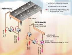
Figure 2:two common methods of liquid back-up control
In Figure2 - Method 1, control valve (B) reacts to the pressure at its inlet. When this pressure is below a predetermined setting, the valve closes off. Control valve (A) senses the pressure at its outlet (receiver pressure) and if this pressure is below a pre-set condition, this valve opens. This combination results in the condenser being by-passed which in turn means that there is no condensing and the discharge pressure progressively rises. This rise in pressure will register on the outlet of valve (A) and cause it to close off, which in turn forces valve (B) to open and allows some of the liquid backed-up in the condenser to drain out. As the liquid is drained from the condenser, more surface area is exposed and the condensing temperature will fall.
The configuration of the controls shown in Method 1 would be suitable for systems which have some condensing duty for most of the day, say 20 hours per day even in winter.
Systems which may switch off for long periods, say over night, will have to use Method 2. In this arrangement the control valve B, sensing pressure at its inlet, is fitted to the inlet to the condenser and a one way valve is fitted to the condenser outlet, (the direction of flow is towards condenser drain.)
The sequence of operation is virtually the same as in method (1) with the valves set at the same settings. However the start up reaction time is very much quicker than Method (1).
In Method (1) the condenser is open to the discharge line at all times and during a cold start when the condenser and liquid in the system are at low temperature there is a significant time delay before the condensing pressure builds up because of the buffer effect of the condenser.
In Method (2) valve (B) is closed and valve (A) is open, discharge gas flows directly to the receiver and pressurises the liquid very rapidly thereby providing the required pressure difference across expansion valves. The discharge vapour cannot flow into the condenser because of the check valve. The disadvantage with Method (2) is that there will be considerable hunting between valves (A) and (B). When the system starts in Method (2), the discharge vapour flows directly to the condenser and pressure build up is rapid. When the pressure setting of valve (A) is reached it closes and valve (B) opens. When this happens, the discharge vapour enters the cold condenser, rapidly condenses and reduces pressure and this reduction in pressure results in valve (A) opening and valve (B) closing. This sequence of events continues until the system stabilises and this can take a considerable time.
Liquid back-up control is frequently used in conjunction with fan cycling control, particularly the method shown as Method (2). It use reduces the amount of fan cycling because the system pressure does not change as rapidly as when fan cycling is used on its own.
Systems of all sizes are fitted with liquid back-up, and pre-set valves for smaller condensing units are supplied by a number of manufacturers. Larger systems usually use adjustable controls.
When designing a liquid back-up system it must be appreciated that the amount of additional liquid to make the system work is considerable, the condenser volume must be taken into consideration and liquid equal to at least 80% of this volume will have to be added to the system. Compliance with codes of practice and refrigerant handling require that sufficient receiver capacity be available to contain the entire system charge.
When setting up a liquid back-up system it is not necessary to set the valves to achieve the summer design condensing temperature. The essential requirement is to ensure that the minimum pressure differential to allow the expansion valves to work correctly is provided. The pressure setting must take into consideration liquid line pressure losses, pressure drop across refrigerant distributors and the capacity of the expansion valve for a given pressure drop.
Note: Electronic expansion valves are not so dependant as mechanical expansion valves on pressure drop to achieve their rated capacity and a lower system liquid pressure can therefore be used. This has the advantage of reducing the liquid charge for the system.
DISCLAIMER: Whilst every effort is made to ensure absolute accuracy, Business Edge Ltd will not accept any responsibility or liability for direct or indirect losses arising from the use of the data contained in this series of articles.
With thanks to Mike Creamer of Business Edge who revisits his Masterclass series of articles, updating and adding to the information which proved so useful to readers when the series was first published over ten years ago. In this reincarnation, the series will cover both air conditioning and refrigeration and serve as an on-going source of technical reference for experienced personnel as well as providing a solid educational grounding for newcomers to our industry.