Rotary vane compressors
The rotary vane compressor employs a series of rotating vanes or blades, which are installed equidistant around the periphery of a slotted rotor. The rotor is mounted eccentrically in a steel cylinder so that the rotor nearly touches the cylinder wall on one side, the two being separated only by an oil film at this point. Directly opposite this point the clearance between the rotor and the cylinder wall is maximum. Heads or end plates are installed on the ends of the cylinder to seal the cylinder and to secure the rotor shaft. The vanes move back and forth radially in the rotor slots as they follow the contour of the cylinder wall when the rotor is rotating. The vanes are held firmly against the cylinder wall by action of the centrifugal force developed by the rotating rotor. In some instances the blades are spring loaded to obtain a more positive seal against the cylinder wall.
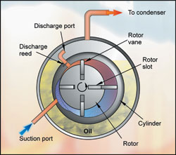
Figure 1: vane type rotary compressor
The suction vapour drawn into the cylinder through suction ports in the cylinder wall is entrapped between adjacent rotating vanes. The vapour is compressed as the vanes rotate from the point of maximum rotor clearance to the point of minimum rotor clearance. The compressed vapour is discharged from the cylinder through ports located in the cylinder wall near the point of minimum rotor clearance. The rotary vane compressor is a rotary positive displacement type, which has the advantage of simplicity where a complex screw or scroll form need not be manufactured. The high sliding speeds at the contact of the vanes with the cylinder walls demand careful design and generally limit this type of machine to smaller compressors such as fractional horsepower units. However, quite large displacement machines of this type have been successfully built and used as boosters. A booster is the first stage of a two-stage compression process. In such applications the loading is relatively light. Where higher compression ratios are required for low temperature applications, it is quite common for rotary vane compressors to be arranged in two- stage configurations.
The rotary vane compressor does not have a sump to contain the oil reserve. The oil is therefore extracted from the discharge gas by means of an oil separator (described later in the series) and continually delivered in a controlled manner to the internal surface of the rotor housing to perform essential lubrication. Some models are now constructed within a body that has an oil reservoir adjacent to the compressor to simplify oil management and to improve the security of lubrication.
Screw compressors
Screw compressors are extensively used in large air conditioning and industrial refrigeration applications. The first practical design of screw compressor was patented by Lysholm in Sweden in 1934 and developed by Svenska Rotor Maskina (SRM). Screw compressors based on the Lysholm design with twin screw rotors were introduced into the refrigeration market in 1958 and found their place in the refrigerating capacity gap between reciprocating and centrifugal machines. Following the use of injected oil for cooling, sealing and lubrication, the versatility, reliability and compactness of screw type compressors has been increasingly appreciated. This has earned them a significant share of the market in a capacity range now overlapping that of the reciprocating and centrifugal machines.
The rotary screw compressor is a positive displacement helical-axial design and is well suited to high-pressure refrigerants and alternative gas applications such as propane, helium, CO2, natural gas and air. In the twin-screw compressor, compression is achieved by two intermeshing rotors housed in a close fitting casing (see fig 2). The male rotor has lobes which are non-symmetrical profile sections formed vertically along the rotor length and these mesh with corresponding recesses on the female rotor. As the rotors turn, gas is drawn through the inlet port to fill the space between adjacent lobes. When the interlobe space along the rotor length is filled the rotation of the rotors moves the end of the lobes past the inlet port so sealing the interlobe space. As the rotors continue to rotate, the intermeshing of the lobes on the discharge side of the compressors progressively reduces the space occupied by the gas causing compression. Compression continues until the interlobe space becomes exposed to the outlet port in the casing and the gas is discharged. The machine has few moving parts (seven): slide valve, two rotors and two sets of heavy-duty industrial bearings. This construction allows the compressor to operate at two-pole motor speeds (3600rpm synchronous) with high efficiency.

Figure 2: screw rotors that form the heart of the Bitzer screw compressor range
Uniform gas flow, unidirectional compression process, even torque and positive displacement through rotary motion contribute to vibration-free operation. The design provides simplicity and the absence of a clearance volume leads to high volumetric efficiency. The screw compressor can be arranged with vertical or horizontal rotors and an illustration of the vertical screw compressor is shown in fig 3.
Capacity control
The screw compressor is able to offer infinite capacity modulation to as low as 10% of full load. This is achieved by means of a hydraulically actuated slide valve in the compressor housing which creates a gap to allow suction gas to pass back to the suction inlet manifold thus reducing the compressor pumping rate. As the gas is released prior to compression, it is assumed that minimal thermodynamic losses occur. The location of the capacity control slide valve is controlled electronically and is determined by temperature, pressure or power input signals for the optimum match of compressor capacity to load variations.

Figure 3: a sectional view of the vertical screw compressor
Single screw compressor
An alternative type of screw compressor has been successfully developed and introduced. This is the single screw compressor. It has a screw rotor in mesh with two rotor seals. An efficient and reliable compressor was conceived by Bernard Zimmern from this known principle in the 1960s.
The essential functional elements of today's single screw compressor are a six-flute driven rotor meshing with two star rotors each having eleven teeth. The star rotors are made from a special synthetic material and the dynamically balanced rotor is made from cast iron. The portion of the casing corresponding to the entry end of the cylindrical main rotor is relieved so that the inlet gas may enter the flutes both axially and radially. The discharge end of the main rotor extends a short distance beyond the points at which the flutes run out; the discharge ports comprising essentially triangular openings in the main rotor casing in this region.
During the compression process, gas becomes trapped in the flutes by the teeth of the stars and is compressed by the face of each tooth until the flute wall uncovers the discharge port, and the compressed gas is completely expelled. The size of the discharge port determines the in-built compression ratio. The compression process occurring on the face of the teeth of one star is exactly duplicated by a series of compression processes occurring on the opposite face of the other star. The existence of two stars thus causes each flute to be used twice in a complete revolution of the main rotor. Furthermore, the symmetry of the compression processes results in zero radial gas pressure loads on the main bearings. Also, because the flutes terminate on the cylindrical surface of the main rotor at the discharge end, it is possible to arrange that both ends of the main rotor are at suction pressure, in which case the thrust load approaches zero. Thus, apart from the weight of the rotor assemblies, the only loading on the bearings arises from gas pressure acting on the small-engaged area of 2 or 3 star teeth on each star. As the single screw is a positive displacement compressor, there are three stages to the compression cycle. The following illustrations in figure 5 will serve to describe these:
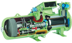
Figure 4: sectional view of Bitzer screw compressor
Suction: fig 5 - A & B
Main rotor flutes “a”, “b” & “c” are open to suction at one end and are sealed at the other end by the star rotor teeth. As the main rotor turns, the effective length of the flutes increases with a corresponding increase in the volume open to the suction chamber as shown in fig 5 - A. As flute “a” assumes the position of flutes “b” and “c” it’s volume increases, inducing suction vapour to enter the flute. Upon further rotation of the main rotor (Fig 5 - B), the flutes which have been open to the suction chamber engage with the star rotor teeth. This coincides with each flute being progressively sealed by the cylindrical annulus housing the main rotor. Once the flute volume is closed off from the suction chamber, the suction stage of the compression cycle is complete.
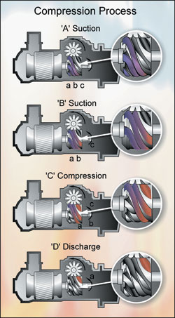
Figure 5: single screw compression process
Compression: fig 5 - C
As the main rotor turns, the volume of gas trapped within the flute is reduced as the length of the flute shortens and compression takes place.
Discharge: fig 5 - D
As the star rotor tooth approaches the end of a flute, the pressure of the trapped vapour reaches a maximum value occurring when the leading edge of the flute begins to overlap the triangular shaped discharge port. Compression immediately ceases as the gas is delivered into the discharge port. The star rotor tooth continues to scavenge the flute until the flute volume is reduced to zero. This compression process is for each flute/star tooth in turn.
As with the twin-screw compressor, this machine is also designed to run at 2-pole 3600rpm synchronous speed and utilises suction gas to cool the 3-phase motor windings. Capacity control is achieved with a slide valve mechanism, which allows infinite modulation between 100 and 25% of full load capacity. Oil is normally injected through the casing near the discharge end of the compressor to act as a coolant, lubricant and sealant. Most of this oil leaves with the compressed gas where it is separated before being cooled and re-injected. Some single screw compressors do not require lubricating oil at all thus eliminating the need for oil control management equipment and leading to higher overall system efficiency.
An oil separation section incorporating a sound attenuation chamber and a discharge gas non-return valve exists within the compressor. The separator also acts as the oil reservoir, has an oil level sight glass and a 150 mesh stainless steel oil strainer. An oil heater can also be incorporated to prevent refrigerant migration and condensation within the lubricating oil.
Suction strainer
In order to protect such compressors from dirt and particles, which may be recirculating with the system refrigerant, an integral suction strainer is incorporated to trap and retain these particles. This suction strainer is normally inaccessible. Where a compressor is installed into a site-built system, an additional suction strainer, which can be easily serviced, should be installed at the inlet to the compressor.
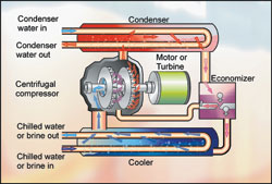
Figure 6: flow diagram of typical centrifugal water-cooled water chiller
Centrifugal compressors
The operating principles of the centrifugal compressor are similar to those of the centrifugal fan or pump. Low-pressure, low-velocity vapour from the suction line is drawn in the inlet cavity or “eye” of the impeller wheel along the axis of the rotor shaft. On entering the impeller wheel, the vapour is forced radially outward between the impeller blades by action of the centrifugal force developed by the rotating wheel and is discharged from the blade tips into the compressor housing at high velocity and at increased temperature and pressure. The high-pressure, high velocity vapour discharged from the periphery of the wheel is collected in specially designed passages in the casing which reduce the velocity of the vapour and direct it to the inlet of the next stage impeller or, in the case of the last stage impeller, to a discharge chamber, from where the vapour passes through the discharge line to the condenser.
The centrifugal compressor is simple in principle and it is a perfectly balanced machine with no contacting compression surfaces. However, because high gas velocities are needed for this process, the centrifugal machine really only becomes effective in quite large sizes. Moreover, a high compression ratio could require many stages of compression. This increases cost and complexity and at the same time introduces more gas friction losses. The centrifugal compressor is very effectively applied in air conditioning applications where the pressure ratio is modest. Even under these conditions, the smaller types utilise speed step-up drives to attain the required compression ratio. Because the refrigerant itself generates the pressure, the vapour density of the refrigerant has to be taken into account in the compressor design and the centrifugal compressor is not nearly as versatile as piston or rotary positive displacement types. Such machines are normally of very large cooling capacity and are designed for substantial cooling loads in large buildings and industrial applications. These are heavily applied in the USA and other countries featuring large buildings operating in high ambient temperatures.
NEXT MONTH: Air and Water Cooled Condensers
With thanks to Mike Creamer of Business Edge who revisits his Masterclass series of articles, updating and adding to the information which proved so useful to readers when the series was first published over ten years ago. In this reincarnation, the series will cover both air conditioning and refrigeration and serve as an on-going source of technical reference for experienced personnel as well as providing a solid educational grounding for newcomers to our industry.