Mike Creamer of Business Edge revisits his Masterclass series of articles, updating and adding to the information which proved so useful to readers when the series was first published ten years ago. In this reincarnation, the series will cover both air conditioning and refrigeration and serve as an on-going source of technical reference for experienced personnel as well as providing a solid educational grounding for newcomers to our industry.
Research and development
I was very involved in the research, development and the launch to the US market of VRF technology in the late 80s. The primary market aim was the supermarket and low temperature refrigeration industry, with a view to eventually taking this to special air conditioning applications.
In order to conduct realistic tests for the r&d programme it was deemed necessary to have a very real refrigeration load against which to run-test conventional systems against the new VRF technology. Accordingly, we constructed our own supermarket, as shown in fig 1.
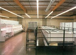
Fig 1: The 'supermarket' created to conduct
realistic tests on VRF technology
Our supermarket had a total floor area of 2,050 m
2 (22,000 ft
2) and included a vast array of display cases, chest freezers, cold rooms and so on. Refrigeration pipework layouts were installed in accordance with typical Safeway store arrangements to ensure that the technology would work correctly on existing evaporator loads in retrofit situations. Lighting loads were also in accordance with Safeway supermarket standards. Heaters and humidifiers simulated occupancy loads.
This test supermarket also allowed us to demonstrate the continuously variable capacity technology in operation under circumstances that were a true simulation of the intended supermarket installations, with clients directly witnessing the performance.
The VRF compressor
VRF technology requires a compressor that can deal with arduous operating conditions. Moreover, such compressors may be required to run at high or low speeds with low through to high compression ratios. The operating envelope can therefore be incredibly wide.
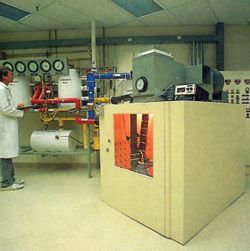
Fig 2: A calorimeter room constructed to
ASHRAE standards
Compressors for critical supermarket, process cooling and air conditioning applications must also be vigorously tested in terms of their safety and in our development work we decided to opt for the ASHRAE test standards against which to approve the compressors.
Capacity and power input data
Given that this work commenced in 1985 (26 years ago!) there was no data available for the capacity and power input of compressors running at various speeds and at a variety of operating conditions/compression ratios. We therefore decided to construct our own calorimeter room in accordance with ASHRAE standards (see fig 2).
The calorimeter room allowed us to set a very precise evaporator load and to carefully measure the heat of rejection at the water-cooled condenser.
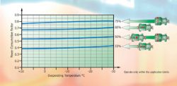
Fig 3: Power consumption with cylinder unloading
Compressors under test were enclosed in a thermal housing to permit the measurement of sensible heat emission from the compressor body and drive motor. Power input and torque measurements via a dynamometer to the compressor were also recorded.
In order to establish the performance of compressors across a variety of refrigerants (R12, R502 and R22) it was necessary to conduct literally hundreds of tests. A single test might take as much as a day to set-up and record and in the early stages it was essential to test a wide range of compressors from various manufacturers.
Compressor types
Given that our initial target was that of medium to low temperature refrigeration, process cooling and other arduous applications, it was necessary to use reciprocating compressors as the foundation of the VRF technology. Scroll compressors were in their infancy at the time and certainly not capable of any reasonable performance at low temperature. Screw compressors were too large and not efficient at reduced speeds and capacity.
The r&d on reciprocating compressors uncovered anticipated but, yet, surprising performance results. When the running speed of reciprocating compressors is substantially reduced, their efficiency is tremendously improved.
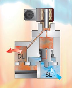
Fig 4: Cylinder unloading
A classic example of this is the application of reciprocating compressors to refrigeration over the last 100 years or so, where most compressors were open drive with a belt and pulley drive configuration. In most circumstances, the pulley on the motor would be much smaller than that of the compressor and the compressor therefore always ran at a speed lower than the motor speed of 1,450 rpm.
Consequently, the efficiency of the slow running compressor was very high and its life expectancy extremely long, provided it was well made and regularly serviced.
Shaft seal leakage
Whilst these slow running compressors ran fairly efficiently, manufacturing precision and shaft seal technology in the early days was simply not as advanced as they are today. Consequently, such compressors often leaked profusely, requiring regular servicing and refrigerant top up.
While we were unaware then that the refrigerant was so damaging to the environment, the ongoing loss of refrigerant was still costly, both in terms of refrigerant and the associated labour for top up, replacing shaft seals and so on. The refrigeration industry was therefore driven to find a solution to this problem and the semi-hermetic compressor was born.
Fig 5: Bitzer's inverter-driven Octagon
compressor is specifically designed for
container refrigeration
The semi-hermetic compressor allowed the compressor and motor to operate as a single assembly within a hermetically-sealed casing, which addressed the problem of refrigerant leakage. The motor housing/compressor casing could be dismantled for servicing and repairs, as could key components like the oil pump.
This arrangement allowed the crankshaft/motor shaft to become one, thus dispensing with alignment problems that apply with direct drive, in-line compressor/motor combinations. Moreover, the leaking shaft seal syndrome now became history.
Unfortunately, the advent of semi-hermetic compressors brought some partially negative results, these being:
a) Refrigerant vapour entering the compressor now had to be drawn over the motor windings in order to remove the rejected heat from the motor. In open drive machines, motor heat is rejected to surrounding air via a motor cooling fan and a finned motor body.
The semi-hermetic compressor therefore further increases the temperature of the partially superheated vapour from the evaporator/suction line and this additional heat energy has to be rejected at the condenser. The condenser is therefore required to be of greater capacity to handle the waste energy from the drive motor.
b) Secondly, the increased vapour temperature results in increased vapour volume and thus the mass flow of refrigerant through the compressor is reduced. Compressor capacity is therefore lower than that of an equivalent open drive machine.
Weaknesses
In the case of semi-hermetic compressors arranged in parallel (or series) within a single refrigeration system, the presence of air/moisture, leading to acid formation, allows the acid-laden refrigerant to attack the motor windings of all the compressors in the circuit. Fully-hermetic compressors experience the same scenario, such as scroll compressors in multi-compressor pack arrangements. Multiple open-drive systems do not suffer from this situation.
Alternative designs
An interesting variant of the semi-hermetic compressor is one in which the crankshaft and motor shaft are as one, but the motor is air cooled and thus does not rely on refrigerant vapour for motor cooling. Given the advances in shaft seal technology over the last two decades or so, the construction of such a compressor is straightforward and is extremely reliable in terms of refrigerant leakage.
Controlling capacity
The vast majority of acr systems are designed to meet operating conditions at the greatest possible heat gain, the highest anticipated summer ambient temperature and the lowest internal design temperature. Based on this information, the equipment is then normally selected to meet the calculated heat gain (kW) under these peak conditions. However, we all know that most air conditioning and refrigeration equipment rarely operates at such extremes, if at all. Even then, the equipment may only be exposed to such conditions for a few days.
Compressors are invariably oversized for most if not all of their operating time. It is also important to remember the following:
a) As ambient temperature and absolute moisture content fall, sensible and latent gains to the conditioned space/coldroom, etc, are reduced. The compressor load is therefore reduced accordingly;
b) As ambient temperature falls, compressor is progressively increased.
When the two effects described in a) and b) are combined, the 'over-sizing' of the compressor becomes dramatic. A fixed speed, cyclic compressor will then need to be switched on and off with increasing frequency or some other means of capacity control will have to be implemented.
Cyclic operation of compressors is very inefficient and also places the compressor under stress. The high starting current can also stress the building's electrical supply and will also increase utility costs per kWh due to higher peak demand loadings. In extreme cases, the available power supply to a building may not be adequate to allow the installation of air conditioning or refrigeration. A solution to this problem might be the installation of an additional sub-station transformer. In one recent case, for only a few split system air conditioners of modest capacity, the local electricity supply company wanted £45,000 for the provision of this!
Oversized compressors can also lead to an unstable refrigeration system, coupled with uneconomical operational running costs, technical problems and failures. Examples of this would be the need for increased defrost time, frozen evaporators on water chillers, etc. Clearly, there is a real need to be able to adjust the refrigeration capacity of a compressor and there are various methods of achieving this. We have covered methods of capacity control in other articles, but some examples include: Hot gas by-pass (excellent control down to 10% capacity - but very uneconomical); use of several smaller compressors to partially match the load (fairly efficient - but will complicate design, build, control, etc); cylinder unloading on reciprocating compressors (reasonable efficiency - but not the highest); frequency inverter drives to vary the compressor speed and thus refrigeration capacity (excellent efficiency and many other benefits).
The cylinder unloading of compressors, to suit system capacity, is a very simple and relatively efficient way of reducing compressor capacity. If a four-cylinder compressor has two cylinders fitted with cylinder unloaders, then the compressor capacity can be reduced to 50% of the full capacity. Meanwhile, the power consumption is reduced to 53% of full capacity (see fig 3).
This slight reduction in operating efficiency is negligible. In reality, when operating on only two cylinders, the condenser becomes generously oversized for this application point and the discharge pressure is dramatically reduced. This has a very beneficial effect on compressor efficiency, which might now rise to 70% or beyond, depending on prevailing ambient temperature. The ambient temperature under such conditions is almost certainly much lower than summer design, which is why the controls will have forced the unloaders to operate on two out of four cylinders. Some of these points also apply to variable speed compressors, to be covered later.
The Bitzer cylinder unloading mechanism is incorporated into a special cylinder head and incorporates an electrical solenoid assembly, which is the only difference between it and a standard compressor.
This simple design concept means that this option can also be applied to existing compressor installations. The control for the unloading solenoids can be as simple as fitting a number of pressure switches into the refrigeration system or could be operated by a more flexible, albeit more complex, PLC or step controller.
The key advantage of this type of system is that the solenoids can be cycled on and off both quickly and frequently in order to match the compressor capacity as closely as possible to the refrigeration system load.
The alternative is to install a larger number of compressors of dissimilar capacities. For example, if a 5 kW, 10 kW, 15 kW and 20 kW compressor pack were to be used, the following capacity steps would be possible: 5, 10, 15, 20, 25, 30, 35, 40, 45 and 50 kW.
However, a larger number of smaller compressors will have limitations on the switching frequency of the compressors, as the electric drive motors have a limit to the number of starts/hour (usually 8-10/hr). In addition, minimum running time (usually 2 mins) means that a compressor could be offline for up to 4 mins, depending on the load change in the system. Under certain circumstances, this will mean that the compressors will not be able to match the refrigeration load variations as closely as the cylinder unloading option.
The unloading system relies on a positive pressure difference between suction and discharge pressure. When a compressor is running and the solenoid coil is energised (see fig 4), the spring-loaded armature inside the solenoid valve lifts and allows discharge pressure to move into the chamber in the cylinder head above the unloading piston. This forces the piston to move down its cylinder and the seat on the bottom of the piston shuts off the suction inlet to the valve plate. With the suction port shut-off, the compressor pistons do not draw any suction vapour past the valve plate and no compression takes place, which thus results in the reduction of mass flow from the compressor and reduced refrigeration capacity.
When the solenoid valve is de-energised, the spring-loaded armature re-seats itself, cutting off the supply of discharge pressure above the unloading piston. The remaining pressure then bleeds through the small pilot hole in the centre of the unloading piston. The pressure is now equalised on both sides of this piston and the pressure of the integral spring forces the piston to rise inside its cylinder. The valve plate suction port is now open to the suction valve reeds. The pistons are able to compress the vapour, the mass flow increases to its original amount and the cylinder is restored to full pumping capacity. The solenoid valves can be operated with a high switching frequency without risk to the compressor, thereby following the system load very closely.
Frequency inverter or variable speed drive (VSD)
The frequency inverter has been extensively used to vary the refrigeration capacity of a reciprocating compressor. One of the advantages of the frequency inverter drive is the ability to operate the compressor above the synchronous speed (provided the capacity of the motor is adequate). Bitzer has further refined the design of its new inverter-driven Octagon compressor range to produce a product that is specifically designed for container refrigeration.
When using frequency inverters with standard reciprocating compressors, the compressor speed can be infinitely varied from about 800 rpm (26.6 Hz) up to 1,750 rpm (60 Hz). When this frequency inverter/compressor arrangement is coupled with a system microprocessor controller/PLC, it can follow the system load very closely indeed. The result is precision temperature control and substantial energy saving.
With this equipment, the compressor speed is precisely controlled according to the system requirement, with either a specific suction pressure or space or temperature being the set point target. The PLC varies the compressor speed via the frequency inverter accordingly. This type of close control is especially suited to systems with a wide load variation, such as central air conditioning plant or central refrigeration plant with a number of cold rooms connected. It is also well suited to multiple evaporator systems as found in supermarket refrigeration or VRF air conditioning systems.
Where air temperature is the target set point criteria, this could be the temperature within a conditioned space. The return air from the space is normally the best place to position the temperature sensor for the most representative reading. In other applications, the leaving air temperature is required to be closely controlled and the temperature sensor would be positioned accordingly. In fluid cooling applications such as water chillers, the leaving water temperature would be the logical position for the temperature sensor.
Each of the aforementioned systems has advantages and disadvantages. Cylinder unloading is very cost effective and can easily be fitted to existing systems. However, there is a slight COP reduction (negligible) and according to the application, there may be a requirement for additional cylinder head cooling, since the heat generated by friction is not being carried away by a flow of refrigerant vapour.
The frequency inverter approach can follow the system load very closely to give an almost flat suction pressure or target temperature profile. The cost of a frequency inverter is the major drawback. It must be remembered that when the compressor is being driven at 100%, due to internal losses within the frequency inverter, the system efficiency is lower than operating the compressor direct-on-line without the frequency inverter. However, given that most systems rarely run at this condition, the substantial savings within the refrigeration cycle itself will normally offset this to a major extent.