Numerous developments have taken place along the way to arrive at the inverter systems we know today but the basic concept remains the same.
With an AC power supply the voltage switches between positive (+) and negative (-) in cycles. With a DC power supply the voltage remains constant at a positive value and it is assumed that electricity flows from positive to negative in electrical circuits.
The compressor motor of an air conditioner was traditionally driven by the mains AC power supply which is supplied at 50Hz in the UK. This is the frequency of the AC wave or number of cycles per second (eg 50Hz = 50 cycles per second).
This frequency (or number of cycles) dictates the speed at which the compressor motor will rotate. Thus in a non-inverter type system the speed is fixed. The inverter makes it possible to change the frequency of the AC supply to the compressor motor thus changing the speed of the compressor to accurately meet the cooling/heating requirements of the space to be conditioned. This is also energy efficient as the compressor operates at a lower speed for most of the time.
The inverter actually consists of two parts, the rectifier circuit (or converter) which changes the AC input to DC and the inverter circuit which changes the DC input back to AC with a variable frequency (see fig 1).

Fig 1
The rectifier circuit
The rectifier circuit, through a system of diodes (one way gates) converts the negative (-) side of the AC wave to positive (+), although this is still not a smooth DC output and still contains peaks and troughs. To smooth out these peaks a capacitor is added to the circuit which acts as a buffer producing a more uniform DC output.
This produces an output similar to a constant DC voltage signal represented by the pink line in fig 1. Although the voltage has been smoothed out the current is still subject to peaks (or surges), which causes a certain amount of inefficiency.
The next step in the process involves changing this DC output to a variable AC output through the inverter circuit. (See fig 2).
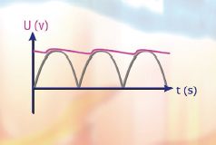
Fig 2
The inverter circuit
The inverter circuit consists of transistors, which are in fact a form of switch and to aid understanding of this concept are shown as switches in the following diagram. These switches can change their positions to produce a positive, zero or negative output, thus simulating a square AC wave. (See fig 3).
By varying the speed of the switching, the frequency of the AC output can be modulated to provide a frequency to match the duty required. (See fig 4). A square AC wave would not be an efficient method of driving the compressor motor and so in practice very high grade transistors are used to provide Pulse Width Modulation (PWM), which gives a smoothed sine wave.
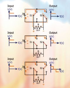
Fig 3
Most leading inverter drives use a very high grade type of transistor known as the integrated gate bipolar transistor (IGBT) this actually modulates the width of each individual pulse to produce the smoothest possible wave. The complete circuit is shown in fig 5.
Pulse amplitude modulation (PAM)
Before understanding Pulse Amplitude Modulation (PAM) it is essential to have a good understanding of how the inverter works (see previous diagram of rectifier circuit).
Fig 6 shows the type of wave pattern for both voltage and current. The current does not follow the voltage exactly and as can be seen from the second diagram the wave peaks quite sharply and then flattens out to zero at the base line. This flat section or the fact that the current wave does not intersect the base line at the same point as the voltage curve causes an inefficiency. To correct this and increase the efficiency of the circuit the PAM technology is applied to the rectifier circuit.

Fig 4
The pulse amplitude is modulated using an integrated gate bipolar transistor (IGBT), the same high grade type that is used for the Pulse Width Modulation (PWM) of the inverted sine wave. The resulting wave is shown in fig 7.
Without PAM the efficiency of the circuit ranges from around 85% to 90%. By applying PAM the efficiency is increased to 99%. Including the smoothing capacitor, the resulting voltage waveform and current waveform can be seen in the following diagram.
Note that the PAM technology is only applied to inverter systems that work off a single-phase power supply and is not applied to three-phase products (see fig 8).
The reason for this is that three-phase provides a more balanced supply and there is no advantage in using PAM.
The reluctance DC motor
The reluctance DC motor, also known as the brushless DC motor, is so called because it has the same make up as a DC motor but actually works from an AC input. DC in this instance stands for digitally commutated.

Fig 5
Reluctance DC motors have a number of features which increase their performance and distinguish them from other motors. Fig 9 is a schematic representation of the motor with the main parts labelled.
As opposed to the usual ferrite magnets that most DC motors use, the reluctance DC motor is equipped with neodymium magnets which are more powerful. Neodymium is a rare material and therefore quite expensive. Curved iron plates are layered to build up the main body of the rotor, which is specially designed, along with the positioning of the magnets, to produce maximum rotational pull, thus reducing the amount of electrical power required to rotate the rotor, increasing the efficiency of the motor (see fig 10).
A row of coils encircling the rotor are positively (N) or negatively (S) charged in a rotational sequence around the rotor to cause rotation. This positive or negative charge on the coils comes from the AC sine wave produced by the inverter circuit, which can vary the frequency to meet the required rotational speed. The sequencing of these sine wave inputs around the coils is controlled by a 32 bit microprocessor giving full control and smooth rotation.
This technology and the additional rotational pull achieved from optimised layout and the neodymium magnets increases the overall performance of the motor to a level considerably higher than a traditional AC motor.
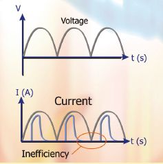
Fig 6
We are now going to look at the delivery of the control system for VRV installations, measure the benefits to the client/end user; and take a look at what technology is available to assist the control requirements. The questions we must answer before looking at the extensive control options available are: Why is a control system necessary?
How will it benefit the client (improved comfort, reduced power consumption, improved management of air conditioned zones through automated operations)? Will the client be better off with an open or proprietary protocol?
Compared with traditional chilled water systems, the VRV system is supplied as a package by one manufacturer. The VRV manufacturer will supply indoor/outdoor units, refrigerant joints, pipe sizes, necessary electrical diagrams and controls based on preliminary equipment selections made by consulting engineers and contractors.
In order to consider the VRV control strategy, we need to understand the basic control strategy behind VRV and the fundamental differences between VRV and traditional fan coil/chiller systems.

Fig 7
Applications using VRV systems to cool/heat buildings have the ability to only request necessary condensing sets and associated indoor units to maintain conditions, while other condensers remain in the off mode, saving energy and minimising C02 emissions. In cases where only two or three indoor units are required to refrigerate, just one compressor may need to operate using as little as 4kW in multi-storey applications. Individual control on low-load operation is just one attribute that sets the VRV system apart from most cooling and heating systems.
Simplified power and control wiring
Three-phase power is supplied to every condenser and single-phase power supplied to each fan coil unit comprises the power circuit. In order for the indoor units to communicate with the condenser a non-polar two-wire control system connects the outdoor units to indoor in a simple daisy chain arrangement.
Any centralised control also shares this twocore system making it easy for the user to retrofit an existing system with a central controller, simply by connecting it to the two-core daisy chain.

Fig 8
In addition standard features such as sequential start and self diagnosis continually monitor the installation. VRV systems are equipped with functionality to give approximately 40 malfunction codes and alarms ranging from minor faults (such as faulty temperature sensors) to major faults (compressor overloads and activation of safety switches). So in the event of system failure, a malfunction code flashes on the local controller indicating an alphanumeric code and location of the fault.
Overview of VRV control strategy
The VRV indoor units are modular by design and capable of connecting up to 48 indoor fan coil units of different profiles and capacities via a network of refrigeration pipes. Each fan coil unit has the unique capability to operate independently to other fan coils connected to the same refrigeration circuit. This is possible because each indoor fan coil is equipped with an electronic expansion valve and three sensors (see fig 11).
The first sensor reads the temperature of refrigerant entering the heat exchanger (T1), the second senses the temperature of the refrigerant leaving the heat exchanger (T2), and the third senses the room Temp (T3). Readings are taken from these three sensors every 20 seconds transferring information to the CPU of each fan coil unit.
The system then computes the deviation between room temperature and set temperature calculating the amount of super heat in the refrigeration circuit to bring the room temperature close to the set point of the room. A signal is then communicated to the electronic expansion valve where the value modulates accordingly.

Fig 9
Simultaneously, the condensing unit receives this data and tries to maintain a constant evaporating temperature/pressure using pressure and temperature sensors located on the suction line. As the pressure in the suction line changes, the system requests optimum compressor speed (or frequency) required to correct the evaporating pressure back to the target suction pressure.
Front end control systems
It is important to remember that although an air conditioning system can have excellent energy efficiency, this is insignificant unless its operation is appropriately managed.
Precise operation and control locally must be supported by a central/local control strategy to get the most out of an energy efficient system. After all the most energy efficient system is one that is switched off!
Local control options
For effective local environment control, consideration should be given to the number of local controllers and the grouping of fan coil units to the controllers - for example, provision of one controller per zone or connecting several indoor units to one floor for a single controller.

Fig 10
In order for any control system to work effectively the operator must be able to use and understand the local controller. Therefore the manufacturer's choice of local controller is extensive and depends on the operation buttons and local familiarisation with the system.
For example, a hotel controller need only provide operation for on/off, temperature set point and fan speed. Whereas an office many require schedule timers, frost protection or mode setting.
Infrared or fixed wired individual controls are optional depending on the type of fan coil unit to be controlled.
Proprietary protocols have developed considerably in recent years. Manufacturers are able to provide cost effective centralised management systems at a fraction of the cost of independent BMS manufacturers. The savings depend on the size of the project and the extent of the manufacturer's equipment installed.
For example, the intelligent touch controller for small to medium buildings and the intelligent manager for larger buildings both use the unique super wiring two-core cable loop. The PC-based intelligent manager provides a monitoring system maximising energy efficiency while maintaining room comfort.
Some of the advanced features include power limit control, which enables systematic management of air conditioning power consumption.
Sliding temperature, which eliminates overcooling and drastic temperature differences with outdoors and local temperatures limit control, provides the appropriate operation management by limiting the maximum and minimum temperatures that can be selected.
It is sometimes all too easy to claim that a building is energy efficient, with the intelligent management system. Daikin is able to divide the total power used by the VRV air conditioners to each and every fan coil unit.
This provides the building manager with a clear picture of the air conditioning energy used in each zone of the building. Tenants in multi-tenanted houses can be shown precise power used by their corresponding units and can clearly see the benefits of operating their air conditioning zones efficiently.

Fig 11
The choice of proprietary systems against 'open protocol' depends on the BMS specification, size of building and different manufacturers' equipment installed. Basic centralised control can be used independently or in conjunction with a central BMS system. The controllers can be used as a back-up for the BMS system or the preferred controllers for localised control settings.
For more extensive interfaces an open network may need to be considered. An open network will provide a method for multiple manufacturers to communicate through a network of gateways.
There are currently two gateways available to create this open network architecture.
The choice is effectively LON or BACnet. Honeywell, Siemens, Invensys, JCL and TAC all promote LON. These are the five largest control films in the first world - excluding Yamatiki of Japan.
In summary, before you prepare a detailed specification for the VRV control system you should be able to provide answers to how your control strategy will achieve the following:
• Can I control individual areas maintaining high efficiencies and occupant satisfaction?
• Will I achieve efficient operation during and outside of normal business hours?
• Will the control strategy improve temperature control and thermal control levels?
• Can the control system contribute to lower maintenance costs?
• Will the additional cost of a central control reduce the running and environmental cost?
• Will the building occupants understand the control strategy?
With thanks to Mike Creamer of Business Edge who revisits his Masterclass series of articles, updating and adding to the information which proved so useful to readers when the series was first published over ten years ago. In this reincarnation, the series will cover both air conditioning and refrigeration and serve as an on-going source of technical reference for experienced personnel as well as providing a solid educational grounding for newcomers to our industry.