VRF systems are normally powered by electrically-driven compressors with an inverter for variable speed control. The GHP is a VRF system, which has the compressor powered by an engine using natural gas as the input fuel. This means that large cooling/heating systems can be installed in buildings, which have only a limited electrical supply. The GHP requires some electrical power for the fans and controls, but this is minimal compared to the power requirements of a conventional VRF, chiller or other type of system.
In winter, the heating performance is maintained in very cold ambient conditions, because the waste heat from the engine is utilised as a secondary heat source to enhance the output of the heat pump.
Gas Driven Heat Pump: technical advantages
VRF technology is well known, and specialist installers are familiar with the installation requirements and the procedures for commissioning. All of these VRF systems are powered by electricity, usually a three-phase power supply. The compressor normally would use 96% of the electrical power of the outdoor unit, the remaining 4% being for the fans and control system.
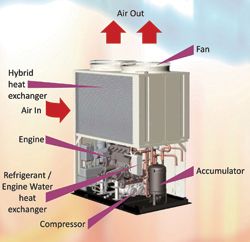
The GHP is a VRF system that behaves in a similar operational mode to conventional electrically-powered VRF systems but instead of using electrical power for the compressor, the GHP compressor is driven by an engine, similar to a car engine with four cylinders, spark plugs, etc.
It is also capable of being controlled at varying speeds, ie, similar to the inverter on an electric system. The engine is directly coupled to the compressor.
The cooling operation is identical to that of a conventional electric VRF system, with a variable speed compressor responding to the combined cooling requirement of the connected indoor units.
The heating operation is similar, but with the advantage of having a secondary heat source, ie, the waste heat from the engine. This waste heat is utilised to enhance the heating performance of the GHP, especially at low ambient winter temperatures, the point at which an electric system is least efficient. The engine coolant is circulated through a heat exchanger to transfer waste heat energy into refrigerant, thus increasing the COP of the heat pump operation.
Furthermore, there is no shut down period for defrosting the outdoor heat exchanger, so the GHP can deliver 100% heating performance. Because the heat source is constant, the warm up time from initial start is also reduced.
Mitsubishi Heavy Industries GHP
In the case of the Mitsubishi Heavy Industries unit, heat exchangers and fans are positioned in the top section, with a sealed engine/compressor housing below. This housing has acoustic insulation to minimise noise break out.
The engine is a conventional four stroke internal combustion engine. It has an automatic throttling device that provides speed control, dependent on the combined demand of the connected indoor units.
The microcomputer controlled system behaves similarly to an inverter system on electric VRF units. The air intake for the engine is at the top of the unit, and passes downward through the centre of the unit to the engine air filter and inlet manifold. The exhaust gases are discharged upwards, and out of the top of the GHP. A small drain outlet is required for the condensate forming in the exhaust.
A large oil reservoir for engine lubrication is included to allow for prolonged operation without topping up.
The fuzzy-logic controller, which combines all the data from the indoor units and outdoor unit, constantly monitors the performance of the engine and the refrigeration system, in order to maximise performance, efficiency, and internal comfort levels. The outdoor unit has a seven segment, six-digit display for ease of component and system monitoring and for fault diagnosis.
Electrical power requirements
Because the compressor is powered by the engine, the GHP uses less then 1kW of electricity to power the fans and control equipment. The power supply is 3-ph + N. Power supplies to commercial buildings are very often inadequate and are often utilised fully for internal electrical equipment.
Electrically powered systems such as VRF and chillers require a substantial power supply, which is often not available in, or near, the building. The cost of installing new power supplies can be up to £100,000, if a substation is required.
GHP uses approximately 10% of the electrical power of a conventional VRF system. Where the supply in a building is limited, the available power can be made available for the building user, for lighting, lifts, IT and office equipment.
Part L regulations
The application of GHP to new or refurbished buildings can provide some margin in the selection of cooling/heating equipment within the parameters of Part L. In particular, the GHP carbon emissions for heating operation are 30% less than the emissions of a condensing boiler. GHP systems are used extensively for commercial buildings such as office buildings, retail stores, car showrooms, schools, universities and hospitals.
The design of the layout of the indoor units, internal refrigerant piping and branch joints is almost identical to a conventional VRF two-pipe system. It is important the pipe sizes are correct and that height and length limitations are not exceeded.
This means the installer's responsibilities are simplified, requiring only to locate the unit and make the necessary connections:
· natural gas supply
· electrical mains power 3ph + N
· two-wire low voltage control cable to indoor units
· refrigerant pipes - two pipes
It is essential the refrigerant piping is installed by a competent and trained engineer possessing a ConstructionSkills or City and Guilds F Gas qualification. Stringent precautions must be taken to prevent the ingress of moisture and contaminants. The gas supply must be installed by a Gas Safe registered installer.
GHP outdoor unit location
As standard the GHP is installed in an open environment. It is essential that there is no impedance to the movement of air circulating through the fans/heat exchangers, or to the intake and exhaust. The GHP can be installed in a perimeter enclosure, but adequate air movement must be provided. It can also be installed in a plant room, but it is imperative the manufacturer's instructions are followed. The GHP is fully weatherproof.
Technical support
The control wiring and method of addressing the indoor units is straightforward, but needs to be properly planned at the design stage. The two wire communications connection is connected to the AB terminals of all the indoor units on each GHP system, and then to the outdoor unit. This method of control wiring minimises costs and provides the user with a very sophisticated microcomputer control scheme.
Fuzzy Logic Controls
VRF systems have issued fuzzy-logic-based controls since their inception. The fuzzy logic control system constantly monitors all functions within the air conditioning system, anticipating change and adjusting functions accordingly, in order to ensure efficient operation.
The SuperLynk control scheme has been developed for the air conditioning market over the last 20 years, being constantly updated (ensuring backward compatibility) to accommodate the progressive demand for increasing energy efficiency.
In a fuzzy logic network, each unit has a unique address. This address collates all variables relating to the specific unit, listing the control status of the unit together with its unique operating variables. Fan speeds, operating mode, coil temperatures, as well as refrigerant pressures, are but a few of the individual unit's unique variables transmitted through the fuzzy logic network.
The network consists of a two-core non-polar wire running between all units within the network. With such a wealth of information available from the network the processor is able to constantly monitor and control the units, as well as establish the root-cause of any fault condition. The unique unit address also provides with pinpoint accuracy where to look for the fault.
Protocol
Most air conditioning manufacturers have their own integral control scheme language called a protocol. This protocol manages the operation of the system including the speed of the fans, the mode of operation and the de-icing and defrost cycles, among others.
These protocols have a plethora of hardware front ends including remote controllers, central controllers, remote sensors and time switches with varying degrees of flexibility and integration.
This hardware is generally suited to human interface; in other words the occupier of the room or building needs to have a physical presence at or near to the controller in order to effect a change to the conditions within the system.
Over the past 15 years there has been an increase in the requirement to fully automate the control of all the disciplines within a building and in some instances completely do away with the human interface.
Full integration of air conditioning, lighting, fire alarm and ventilation systems has been developed in order to optimise the efficiency and overall running costs associated with the services within the building. With the emergence of these types of systems came the necessity to interface between one control protocol and another.
Most protocols are licensed and require a contract between two parties in order to facilitate an exchange of information between them. There are currently two types of protocols 'open' and 'closed'.
· The open protocol has the language made available for all to see with a fee involved in 'binding' together each piece of information between the two protocols.
· The closed protocol is not made publicly available and involves the specific development of an interface between the two protocols. There is the additional cost of each protocol owner developing a mutually acceptable interface. One of the major worries for every manufacturer is the possibility that revealing their own protocol to another source could corrupt the integrity of their own programming. If the complete protocol is released, the new front-end protocol could influence the integral control of the system with the capability of changing variables, safety procedures and other system functions.
With thanks to Mike Creamer of Business Edge who revisits his Masterclass series of articles here, updating and adding to the information which proved so useful to readers when the series was first published ten years ago. In this reincarnation, the series will cover both air conditioning and refrigeration and serve as an on-going source of technical reference for experienced personnel as well as providing a solid educational grounding for newcomers to our industry.