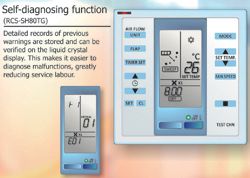
Most people in the industry are familiar with conventional two pipe systems, but are perhaps unaware that the Mitsubishi KX range has features which have been developed to ensure extended reliability, and easy access to servicing and system monitoring.
The KX2 outdoor unit has a 3 x 7 segment LED display which shows the following information:
· Inverter frequency
· Heat exchanger temperature
· Outdoor temperature
· Compressor dome temperature
· Compressor discharge temperature
· Compressor current (fixed and inverter)
· Indication of liquid injection
· HP protection normal or high
· Number of connected indoor units
The sequential display can be viewed through a small aperture without removing the outdoor unit casing.
RCD remote control
A unique feature of the Mitsubishi remote control is the air temperature sensor, which can be seen in the bottom right hand corner of the controller casing. Normally the return air sensor in the indoor unit would determine the cooling or heating requirement, but in some applications, it is preferred to use the remote sensor, for example in ducted systems. This is achieved by setting one of the dip switches in the RCD.
In addition, there are a series of 'jump wires' which if cut will disable the return air temperature display, the air swing display, and the timer setting - thus simplifying the viewed data of the RCD.
The RCD remote controller also has a dip switch, which makes the unit operate only in cooling mode. The heat mode from the controller display is removed, and the heating signal is disabled.
Forced heating/cooling
It is often a contentious issue where two-pipe systems are fitted to buildings, which should have been fitted with a fully flexible three-pipe system.

This is often done where costs are required to be significantly cut at the last minute. On a two-pipe system, indoor units connected to a two-pipe outdoor unit can only operate in the same mode, ie all in heating or all in cooling.
Where there is a requirement to change from heating to cooling eg in spring and autumn, there is often conflict between the occupants in different areas.
The Mitsubishi KX two-pipe system can be switched into forced cooling or heating using the winter/summer switch in the outdoor unit.
However, it is usually preferable to do this remotely inside the building, either manually or using an averaging thermostat, which can operate a reply to switch the cooling/heating mode.
VRF Systems, since their inception, have utilised electronic expansion valves (EEV) in their indoor units to control exactly the optimum amount of hot gas or liquid refrigerant entering the indoor unit heat exchanger. The basis of this monitoring of refrigerant flow is dependent on the differential between the return air temperature and the set temperature.
The fuzzy logic employed in the system controls also has the effect of remembering the room characteristics, and response times, associated with the amount of refrigerant flow, and will adjust the valve opening to suit the room condition. As the valve openings in all of the connected units are constantly changing, and require differing amounts of refrigerant, the demand frequencies actuated by the valve openings are relayed back to the outdoor unit processor, which will then determine the compressor speed to deliver the required amount of refrigerant to the connected indoor units.
Another consideration is the over sizing of indoor units to meet extreme heating or cooling requirements. For example, an office on the corner of a building which has a high proportion of glazing may require say 7kW of heat for the first few hours each day in winter conditions. Once the room is up to temperature, and internal and solar gains take effect, the heating requirements may reduce to say 2.5kW. If the 7kW heating device were controlled by on/off thermostat control, the internal temperature would swing excessively. The automatic adjustment of heating output (or cooling output) results in a stable temperature condition, creating a far more comfortable environment for the occupants. Also the energy which would wasted in winding up or winding down a fixed capacity system is eliminated.
Thus the optimum amount of energy is used to power the compressor, minimising energy wastage, especially at varying capacity requirements through part load conditions.
Pipework layout
The installation of two-pipe system pipework is fairly straightforward. Care must be taken to ensure the piping is of sufficient diameter relative to the downstream capacity of the connected indoor units. 3D applications engineers frequently provide pipework schematic drawings which clearly show pipe sizes for the different parts of the system.
The cleanliness of the refrigerant pipework is extremely important. There is still a great deal of ignorance about using a nitrogen purge when making brazed joints. Many so called engineers think it sufficient to make brazed joints without any nitrogen purge, and then blow it through with nitrogen afterwards.
The amount of oxide particles which form on the internal surfaces of the pipework is often overlooked by many installation engineers and, of course, the refrigerant is an extremely good cleaning agent which clears away these contaminant particles.
So where do they go if the pipework system is sealed? The answer is in the valve seats, the capillaries of the reversing valves, the oil ways, and worst of all in the compressor windings. All this means the valves will eventually jam, or the compressor will fail due to oil starvation, or restricted refrigerant flow. The contaminants will also eventually form an acid with the refrigerant oil, which will in time break through the insulation of the compressor windings.
Engineers usually blame poor manufacturing quality, and manufacturers will in turn blame poor standards of installation, but if one were to witness the high amount of rubbish that is sometimes found inside refrigerant piping, it beggars belief that the system has operated at all.
Three-pipe systems will always have distribution controllers fitted. These devices can be located in ceilings, risers or enclosures and provide each indoor unit with hot gas or liquid refrigerant from the three-pipe system connected to the outdoor unit.
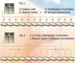
Mitsubishi Heavy Industries (MHI) offers several alternative of piping layout, which gives the designer the opportunity to minimise the overall length of piping and more significantly the number of brazed joints required.
Some manufacturers offer only one distribution controller for each indoor unit, which can result in a huge number of brazed joints. While other manufacturers offer all indoor units connected to one central distribution controller, this can involve extra pipework and long response times where there is an extended length of connecting pipe to the indoor unit.
MHI provide s the option of single- and connection distribution controllers. In fig 1, a conventional system of 12 indoor units with individual controllers is illustrated. There is also the option of MHI providing connection with two six-way distribution controller.
Obviously, the risk of leakage and copper oxide contamination is proportional to the number of site brazed joints. There is the cost consideration of making numerous brazed joints (and flared joints) and their subsequent leak testing.
MHI also provides single, two-way and fourway distribution controllers, which can be applied to various building layouts, whilst minimising the overall length of refrigerant piping. Extended lengths of refrigerant piping will reduce the efficiency of a system, and compromise the response times and degree of control at terminal units at the extremities of the piping system.
Totally flexible control
VRF three-pipe systems can provide cooling and heating simultaneously at any connected terminal unit. So, if some occupants require heating, others can have cooling, without any conflict between them. Furthermore, the heat energy taken from the warm areas of the building can be utilised to provide heating for the cooler areas of the building, thus reducing overall energy costs.
Many modern office environments are filled with electrical equipment, which create constant internal heat gains. Where buildings are well insulated, these heat gains are often sufficient to maintain comfortable temperatures in winter, apart from the initial warm-up period in the mornings.
So for many months of the year a mixture of heating followed by cooling is often required, and the installed system is required to deliver heating or cooling at any time. This is also the case for hotel rooms, retail environments and many other applications of VRF.
Many large projects are designed and specified by consultants. Where the VRF system is the only method of cooling and heating a building, it is normal for a consultant to specify VRF three-pipe systems. This is because of the mixed requirement due to internal heat gains, as mentioned above.
However, the client - whether a developer, building owner, or tenant - will often object to high cost and immediately demand substantial cost reductions. The three-pipe system gets changed to a two-pipe system, the consultant raises all the expected objections and possibilities of conflict, but is overruled because of the cost issue. And so the budgets may be satisfied, but the building user, and the staff in particular, are far from satisfied.
Product support from the manufacturer and distributor will minimise the operating risks. VRF systems provide an excellent solution for heating and cooling buildings. Sometimes they are the only solution available to comply with energy consumption limitations imposed by Part L of the Building Regulations.
With thanks to Mike Creamer of Business Edge who revisits his Masterclass series of articles here, updating and adding to the information which proved so useful to readers when the series was first published ten years ago. In this reincarnation, the series will cover both air conditioning and refrigeration and serve as an on-going source of technical reference for experienced personnel as well as providing a solid educational grounding for newcomers to our industry.