Mike Creamer of Business Edge revisits his Masterclass series of articles, updating and adding to the information which proved so useful to readers when the series was first published ten years ago. In this reincarnation, the series will cover both air conditioning and refrigeration and serve as an on-going source of technical reference for experienced personnel as well as providing a solid educational grounding for newcomers to our industry.
VRF technology has been available in commercial form since the 1980s and has progressively developed into a very sophisticated and reliable system of air conditioning for multiple room applications, large open plan offices, hotels, leisure centres, etc.
VRF technology can be applied to three fundamental application areas:
· Comfort air conditioning
· Process cooling
· Refrigeration
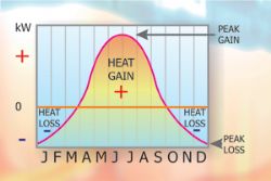
Fig 1: seasonal heat gain and loss
Comfort air conditioning
In this application we see an annual heat gain/heat loss pattern that commences with heat losses from the conditioned space/building during the start of the year, moving to heat gains through the summer cooling period and falling back into a heat loss situation for the remainder of the year (northern hemisphere). This process is illustrated schematically in fig 1. It can be clearly seen that where heat losses are concerned, these range from zero kW to a peak negative kW value. The reverse is true where heat gain is concerned, these ranging from zero kW to a peak positive value kW.
If such an application is to be handled by an air conditioning system that provides both summer cooling and reverse cycle heat pump winter heating, it is clearly evident that the system will have to handle these extremes of heat loss and heat gain.
Indeed, it is also possible that such a system will have to handle heating and cooling requirements within the same day under certain UK and European weather conditions/applications.
In the days preceding the advent of VRF technology, such applications would be handled by single systems featuring one or more compressors. In the case of a single compressor system, the capacity of a system would certainly be matched to the peak heat gain (or peak heat loss) when sizing and selecting the equipment.
However, it is obvious that as the heat gain/heat loss load diminishes, a single fixed speed compressor air conditioning system will become oversized for the application and will therefore be compelled to run in a cyclic (on/off) fashion in order to avoid excess overshoot/undershoot of the design temperature.
As the heat gain/heat loss levels decrease towards zero, the cyclic operation of the plant will become progressively severe. In order to avoid compressor failure through excess and numerous starts/stops per hour, an anti-recycle timer is required to limit the number of starts to somewhere between 8-10 per hour, or some similar value according to the manufacturer.
A single fixed speed compressor system has two capacity levels, these being zero and 100%, under steady-state entering air conditions to the evaporator and to the condenser. The load profile on the space to be conditioned, however, is infinitely variable. Fig 2 combines an illustration of the capacity of such a system and the load profile of a large office space.

Fig 2: excess capacity
This illustration clearly shows the severe mismatch between what is required for the application and what is provided in terms of the air conditioning system. It is this very situation that exists in literally millions of air conditioning and refrigeration installations.
Temperature control
Given that temperature control is the primary objective of such a system, one must find a way of dealing with the paradox of on/off capacity control and an infinitely variable load pattern. This is achieved by cycling the compressor on and off frequently during low load conditions and with decreasing frequency as the load increases towards a closer match with the capacity of the system.
The cyclic pattern of the compressor is broadly shown in fig 3. In this case the load has been shown as a simple symmetrical curve with a midday peak in order to illustrate the related and equally symmetrical change in compressor starts per hour to meet the changing load. At peak load, the compressor is running continuously (zero starts per hour) and as the load approaches 100 kW, the number of starts per hour is at its highest. However, this situation would not be allowed in real applications since this would result in excess wear on the compressor and ultimate compressor failure. The anti-recycle timer will limit the number of starts and will force the compressor to an 'off' condition, even though it is in reality required to be running, since the room temperature will be above the control set point.
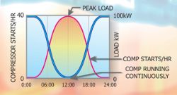
Fig 3: compressor starts
A three minute anti-recycle time is quite common but varies from one manufacturer to another. Given that we are forced to consider such a measure, the result on temperature control will not be as desired. But, for comfort air conditioning, it has been historically accepted that a single, fixed speed compressor system will provide a fluctuating temperature control that is broadly accepted by the industry and is largely unnoticed by the customer.
Fig 4 shows a typical room temperature pattern in relation to the control set point for a cyclic system. In this illustration, we have a room temperature control set point of 22°C but the temperature maintained in this space will fluctuate by around 3 K, ie 1.5 K either side of the set point over time. The degree of temperature swing and the cyclical frequency (time) will vary according to the installed equipment capacity and the application.
Process cooling
In this area we are assuming that there are no heating requirements. Process cooling requirements can range from a steady state situation to highly cyclic loads. Process cooling may also require fine and accurate temperature control. In order to meet both of these key requirements it is desirable to have a cooling system with the ability to respond quickly and accurately to changes in the thermal load, whilst maintaining the desired set point temperature. Again, fixed speed cyclic systems are not ideally suited to such applications.
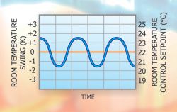
Fig 4: room temperature swing
Commercial/industrial refrigeration
Refrigeration applications are extremely diverse ranging from industrial to commercial supermarket systems and cold storage. In many of these applications, there is normally some form of constant base load with the overall load continuously varying according to a number of factors.
Taking a simple cold room application, the thermal load through the structure of the cold room will be fairly steady state; this varies directly in accordance with fluctuations in the surrounding temperature. If the cold room is located indoors then this is likely to be quite stable. With larger external cold rooms subject to swings in ambient temperature and solar gains the load through the fabric of the cold room will be more volatile.
Infiltration, as a result of door openings, will cause brief fluctuations in sensible and latent gain. Occasional product loading, where the product is delivered to the store at a higher temperature than the storage temperature, will cause further load changes. If serious fluctuations in cold room temperatures are to be avoided, then it is desirable to have a non-cyclical system. However, where food storage is concerned, provided the minimum storage temperature is not exceeded, it is normally permissible to set the control set point such that any swing in temperature causes the refrigeration system to overcool beyond the set point thus preserving the food in a safe condition.

Fig 5: coldroom temperature swing
This overshooting of the set point, however, is very energy-wasteful, since the refrigeration system must run longer and harder to achieve the lower temperature and will do so at lower than required suction pressures, this having a partial impairment upon the compressor efficiency (see fig 5).
The set point in this example is -21°C and if the swing in cold room temperature, as a result of cyclic behaviour, is 3K, it will be necessary for the refrigeration system to drive the cold room temperature to as low as -24°C to ensure that the maximum allowable cold room temperature of -21°C is attained.
Systems where such a conflict between the equipment and the application requirement exist can't cope and the result is poor temperature control and excess energy consumption.
Where comfort air conditioning is concerned, room heat gains experience the majority of load swing as a result of solar gains and solar movement, coupled with fabric time lag. Where a conditioned space has one or more external walls, including glazing, the solar gains will bring about a fluctuating heat gain which varies with orientation, month of the year, time of day, colour of external wall material etc.
Solar gain through glazing varies according to glass type, tinting, reflective capabilities, single versus double glazed, blinds/no blinds, etc. A percentage of the glazing area may also be shaded by overhang or by architectural shading louvres, which will have some diminishing effect on solar gain through the glazing.
Solar radiation striking external walls will be converted to sensible heat, resulting in a high surface temperature on the external wall surface. This sensible heat progressively works its way through the fabric, but there is a time delay in the realisation of the heat energy on the inside surface of the wall, and ultimately to the room. This time delay or 'time lag' is widely variable according to the construction materials used and may range from as little as 30 minutes to as much as 11 hours, for example.
Solar radiation striking the glazing passes through instantaneously to the conditioned space and is realised as sensible heat energy when it strikes the internal surfaces of the conditioned room.
The calculation of these dynamic and constantly changing heat gains is a very complex procedure and must be conducted correctly. The CIBSE Design Method is a well-established and proven process for conducting such calculations. Whilst some consulting engineers still perform these calculations by hand, the majority will now be using advanced software engineering calculation tools for such procedures.

Fig 6: office heat gain periods
Clearly, a cyclic air conditioning system for applications with constantly changing gains and losses is not an ideal solution. Yet we have lived with this situation for many decades.
Where a number of rooms with external walls and glazing are to be served by a common air conditioning system, the cyclic nature of the heat gains becomes much more complex. For example, if one group of rooms each has a single external wall facing east and another group of rooms each has a single external wall facing west then, given that the sun cannot be in two places at the same time, the loading on the complete set of rooms will form an entirely different total value and load pattern when compared to the individual loads and patterns for each room.
This is well illustrated in fig 6, where eight rooms are arranged in two zones in respect of the ac system. The peak loads and the peak times for each room are illustrated and it can readily be seen that the two outdoor units serving these two zones experience heat gains entirely different from the sum of the loads for all rooms.
Indeed, the peak times at which these zone loads occur are very different from the peak times experienced within the rooms themselves. This phenomenon is known as the zone diversity load and the appropriate software will calculate this complex pattern and peak value/time for us. Such software will also calculate the floor diversity load and the entire building diversity load.
In such circumstances, a cyclic on/off system will not provide the desired temperature control or the energy savings achievable with alternative forms of capacity control.