THE degree of mixing, throw, penetration and the velocity of the air into the occupied zone may be significantly altered by the selection of hole patterns, of which there are three types - low velocity, medium velocity and jet.
For a given metre length of ductwork the jet option has continuous rows of holes, whereas, the medium velocity has the rows of holes interspersed with space with no holes (approximately 1?5 of its linear length) and the low velocity option has equal groups of holes to an equal length of spaces with no holes.
The jet option gives purely two dimensional mixing. The medium velocity option has a partial degree of three dimensional mixing and the low velocity option has full three-dimensional mixing. Having a space with no holes allows for greater induction of air and the longer the space the greater the degree of mixing.
The High Impulse system has proved successful for use in warehouses. Here the high impulse ducts tend to be placed at low level above or even in the racks. The ducts provide a high degree of mixing of the supply air with the room air at low level, resulting in the mixed air being at a temperature very close to that of the room air and then the air simply rises through the stack effect.
This works equally for heating or cooling. The extract grilles are normally at high level and because of this the air distribution is so uniform, only a few extracts are required. This application has achieved 0.5°C temperature gradient over 19,000mm, which is good especially if the stored product needs to be kept within close temperature tolerances.
Directional jet nozzle ducts
The Low Impulse option is only suited to cooling, ventilation and tempered air supply, since the supply air moves into the room space in accordance with its own density relative to that of the room air. The cooler the temperature of air the heavier it becomes and, conversely the warm air would rise to the ceiling.
There is also available on the market a hybrid system which combines some of the features from both systems. The new system utilises directional jet nozzles incorporated within a permeable textile, so whilst a proportion of the air is diffusing through the textile the remainder is jetting out of the specially developed conical nozzles. The nozzles are providing the supply air with considerable directional impulse, whilst entraining some of the supply air that has diffused through the textile and at the same time entraining room air.
This action creates a dynamic mixing of room air with supply air and sets up a good degree of circulation, which means that this system can be used for heating as well as cooling and ventilation, whilst retaining the positive textile duct characteristics, such as, being easily washable and free of condensation.
A further derivative is the use of High Impulse fabric with the nozzles which will provide a system whereby all the air is jetted from the nozzles. This has been beneficial in projects that required considerable throw such as in tall buildings, e.g. a warehouse where the ducts have to go at high level. High-level ducts in a warehouse project are mainly used where it is not possible to have High Impulse ducts at low level in the racks.
Advantages over conventional systems
Textile ducting may not be cheaper metre for metre relative to rigid ducting but can actually offer savings of 20-50% by the time all the costs for rigid ducting have been added up. Such additional costs might include:
• Grilles and diffusers • Extra bracketary for secure mounting • Extra time needed for installation • Time and materials for painting • Time and instruments to commission a rigid duct system • Time and materials to insulate (if required) and • Any special treatments that may be deemed necessary (i.e. anti-corrosion in swimming pool halls – fabric ducting is non-corrosive)
Because of the uniform air distribution provided by the textile or fabric ducting, very few extract grilles are required.
Noise can be a big issue for rigid ducting due to hard surfaces, sharp edges, and vibration. These do not apply to textile ducting since it is soft. Reverberation is not an issue and it has been measured that a textile or fabric ducting system can provide attenuation of approx 3dB. This noise attenuation should not affect the size of any silencer that is required for the application.
Permeable type textile ducting is free of condensation since there is no heat transfer across the surface of the duct. As the textile is permeable along its entire length and circumference, the supply air is of the same temperature on both sides of the duct.
Law requires that all supply ducting shall be cleaned regularly and a textile or fabric ducting system is easily removed, cleaned and refitted at a fraction of the time and cost of a rigid system. Different applications call for different materials.
A clean room demands a non-shedding material. An explosion proof area will require a textile that has the ability to discharge static electricity to earth, usually by the means of stainless steel threads. It is recommended that the materials used for the low impulse textile ducting are 100% food quality of manmade flame retardant polyester, flame retardant to DIN 4102 class B1.
Trevira CS is a flame retardant polyester yarn which is now a European standard for low impulse textile ducting. This material being non-organic and man-made means that it will absorb virtually no moisture.
Furthermore, it is important that the textile duct material must not be wholly or partly made of natural fibres as these provide a food substance for micro-organisms and with the presence of moisture they will multiply.
Treatments can be applied to natural fibres such as an antibacterial agent. However, it is not possible to be exact as to how long these agents will last and particles of the chemical agent may become airborne. If polyester is used such agents are redundant and unnecessary. Polypropylene is another possible fibre; however, this can be disadvantageous on the basis of its age-hardening characteristics with exposure to UV light and the difficulties experienced with colouring the fibre.
The textile should be specifically woven for this intended purpose so that it has the correct permeability and has an extended surface area by the means of a corrugated texture. This texture minimises clogging and the depreciation of the air volume being circulated in the room.
This is particularly relevant in circumstances where no other filters are possible, ie ceiling-mounted coolers and fan coil units. The textile should be woven to exacting standards. This is important so that the permeability of the textile is consistent throughout the entire duct section and also that the textile is known to be durable and strong. It is vital that the textile duct manufacturer has a full range of materials of different permeability grades available to ensure that the correct static pressure can be achieved for a certain air volume and certain duct size.
Dimensional stability
It is critical that the textile has sufficient stability to endure the washing process. Allowable shrinkage rates should be a maximum of 0.5%.
Colours
The ducts are available in standard colours. However, any colour according to either RAL or Pantone numbers is possible – a range of approx. 1,600 colours are available.
Duct sizes
Standard duct sizes range from 200mm dia to 1,600mm dia with intervals of approx 100mm; however, this does not preclude other sizes.
Precautions
It is important to recognise that a textile duct system is essentially a means of air distribution rather than air filtration. However, the textile duct does have an effective filtration capability. The air handling plant should provide the filtration (to a minimum of F7, BS EN 779 - ISO Eurovent EU7) to ensure that the textile duct does not act as the primary filter.
This will increase the time between laundering. This may seem a high level of filtration but it is now more common with the lessening quality of outdoor air and demands for higher quality within the built environment.
It is not uncommon for the end-users to choose the semi circular type over the circular type on the grounds of aesthetics, however, both semi and full circular should be considered carefully. The full circular type can be more practical in circumstances where ceiling height is not a factor. It can also be far more cost effective.
Coloured textile ductwork is recommended since white ducting will eventually show greying despite being clean and safe. The manufacturer will provide a washing and maintenance manual. Clean rooms of classification 100,000, 10,000 and 1,000 can be installed with non shedding textile ducting and these are usually white and won’t suffer the greying phenomenon.
Velocities and pressures
The following parameters are recommended for sizing a textile duct ventilation system:
• The textile duct inlet velocity should be a maximum of 7m/s. This velocity also applies to every section of ductwork in order to avoid wasting fan power whilst minimising duct sizes. An exception to this rule is where a higher velocity is used there must be an equal compensating factor, typically a greater static pressure to prevent textile ductwork fluttering or pulsating.
• When textile ducting is combined with rigid ducting to serve noise sensitive areas, it is usual to work on lower velocities as the rigid ducting may otherwise cause unwanted noise. These velocities are typically between 4-5m/s.
• The normal static pressure values are 70-125Pa. Recommended values are 80-110Pa. These figures do not take account of a textile plenum (header duct); the header provides a means by which to distribute the air to the various textile ducts. The plenum pressure loss is typically between 45-100Pa, so it is conceivable that the external static pressure (ESP) required at the entrance to a complete system with a header could be between 115-225 Pa.
• The static pressure for the high impulse systems is often higher than that for low impulse as it is this pressure that determines the throw and mixing performance of the system. Typically high impulse duct pressures are 90-150Pa.
• There is a ratio between static pressure and dynamic pressure that must be applied; the approx static pressure should be equal to or greater than 2.5x dynamic pressure (dynamic pressure = 0.5pV2). In long buildings (say, 40m- 100m) requiring close control conditions, this ratio of the pressures is also important to achieve even air discharge per each linear metre of textile or fabric duct, typically the ratio needs to be 1:4.5.
Laundering
Textile and fabric ducting offer the benefits of being easily removed and washed in a standard washing machine. Laundering is typically carried out once a year following the instructions provided by the manufacturer. This frequency of cleaning is very similar to that of rigid ducting in compliance with the directives of the H&S Executive.
Increased frequency of laundering may be necessary depending on the airborne contamination level and the grade of the filtration used in the ahu. In the food industry more frequent washing will be required.
To facilitate laundering and maintenance it may be necessary to have at least one of each different textile duct size and type held in stock as a replacement. This is particularly relevant to buildings that operate continuously and where maintaining the environment is crucial. Sufficient textile ducts should be operational to ensure that the specified design room conditions are met during maintenance and laundry.
Suspension systems
This should be selected from the manufacturer’s range to best suit the application. The suspension system should allow for the ducts to be easily removed with minimal interruption to the room’s operation.
The materials used for the suspension systems should take into account the room’s environment and any cleaning methods/agents. Anodised aluminium profiles are now most commonly used. For installation where access is not easy due to machinery and equipment, it can be pertinent to choose a suspension system that allows the textile duct to slide as it is not always practical to access every metre of the suspension system.
Information required for system design: • Plan view with dimensions • If heating, side elevations with dimensions • Room and supply temperatures • Air volume flow rate – intended • External static pressure • Type of air handling plant and location • The purpose of the area • The activity of the room occupants • What room environmental conditions are needed
Delivery to site
The system is delivered to site as a complete kit and the suspension system should already be cut to length. Once the suspension system has been installed the textile or fabric ducts simply require sliding onto the track. If the system is any more complex than separate straight ducts then drawings will have to be provided to show the layout along with dimensions.
Every delivery will include mounting and washing instructions, which must be passed on to the end user. When installing the ducts it is important the ducts are raised out of the boxes and straight into the suspension track, ensuring that the ducts do not come in to contact with a dirty floor.
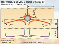
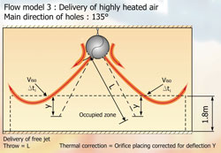
Fig 2 Flow model 3 delivery of air

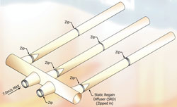
Twin ducts with 30-45 degree bends. This may be several reasons- to avoid obstructions or to widen the spacing between ducts to achieve an even cover of air distribution. The angled bends, as opposed to 90 degree bends significantly reduce the pressure loss and save fan motor energy.
Semi circular textile duct system with a textile plenum, mounted to the ceiling. The air from the air handling plant enters the header via a rectangular inlet socket in the roof of the plenum duct. Recommended max inlet velocity is 4m/sec
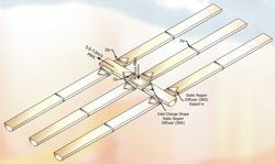
A system using a textile plenum (header duct) for the purpose of distributing the air evenly to each textile duct. The plenum incorporates conical inlet and outlet sockets; these are used as they reduce air turbulance and reduce the pressure loss
A semi circular textile duct system with plenum that is fed horizontally. Again, the system is mounted to the ceiling
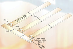
The velocities indicated are recommended maximums. The minimum velocities are not critical in the same way and these could be taken as half of the maximum velocity. The figures on the illustrations show the normal positions for zippers and static regain diffusers.
Zippers should be included in the textile duct design to allow for ease of installation and maintenance. Zippers should be positioned every 5-10m depending on size of the textile duct. Zippers may also be required at strategic positions, eg at the inlet connection to facilitate ease of connection to metal supply spigot; at an outlet socket from textile plenum (eg 90° bend and change of duct size); before and after a duct bend; and at the position where a static regain diffuser (SRD) is required.
SRDs are conical air straightners made from a man-made washable polyester mesh. The SRD fits inside the duct and is therefore not visible from the outside. The air flow in the ducts passes through the mesh which acts to even the air flow velocity profile inside the duct and therefore reduces air turbulance.
With thanks to Mike Creamer of Business Edge who revisits his Masterclass series of articles, updating and adding to the information which proved so useful to readers when the series was first published over ten years ago. In this reincarnation, the series will cover both air conditioning and refrigeration and serve as an on-going source of technical reference for experienced personnel as well as providing a solid educational grounding for newcomers to our industry.