Textile-based air distribution
Textile ducting, or “air socks” as they are more affectionately known, has been around for more years than people would believe and yet still it is new to many people in our industry. One early record of textile ducting being used is in 1955 for a cotton mill in Germany.
People who are aware of the product normally only associate it with the food Industry and sometimes the textile Industry. Although they are two classic applications, there are many more. By means of strategically-positioned nozzles or holes in specially selected materials, for which the combinations and permutations are endless, virtually the whole spectrum of air distribution requirements can be met.
Textile ducting has the ability to create a uniform air distribution throughout the room by virtue of the fact that the entire length of the duct is used for discharging the supply air into the conditioned space, this being impractical or very expensive for many conventional rigid duct systems.
The exception to this is where the textile duct maybe used for displacement ventilation. Here, smaller air volumes can be used with larger temperature differentials dropping the supply air into the occupied zone away from room occupants and then push the warm air to the extract grilles. Displacement ventilation is very efficient for applications where there are particularly high heat loads such as in TV studios, computer suites or printing shops.
In such applications, by the very nature of the principles, the temperature across the area will have a wider band of temperatures and typically there will be a blanket of warm air just below the ceiling; the ceiling being where the extract grilles are normally to be positioned.
Types of ducting
In the main there are two types of textile ducting: The first being “low impulse” and the second “high impulse”. The former type is a permeable woven textile through which the air diffuses at a very low velocity, typically 0.07-0.11m/sec.
The “high impulse” type takes the form of a non-permeable material into which 5mm diameter holes are strategically punched in specifically designed patterns, these hole patterns are critical in achieving the required air distribution and the correct level of comfort specified for the occupied zone.
Design considerations
Although, the air is discharged through the textile duct surface at very low velocity this property alone is not enough to guarantee a draught-free environment. Similarly, for high impulse type of ductwork, careful calculations are needed to ensure that the air velocity is in accordance with the comfort required.
These calculations refer to the throw, penetration, relative air density, hole pattern, duct static pressure, and the orientation of holes.
It is for this reason that an assessment for the area must be made, and the following parameters evaluated: cooling/heating W/m2 length duct; cooling/heating W/m2 of floor area; air volume per metre length duct; room temperature; supply air temperature; positioning of the ducts; required room conditions; activity of room occupants; clothing of room occupants; purpose of the room; objectives of the cooling/heating capacity.
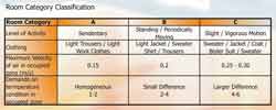
Table A:Room category classification
With this information, reference should then be made to the information contained in Table A in order to determine the room category.
If this design procedure is not followed then the project will inevitably comprise either too little ducting or too much ducting, neither of which is desirable and most probably the quality of the room environment will suffer.
Low impulse
This system has the ability to handle large volumes of supply air and high room air change rates; the reason for this is attributable to the extensive surface discharge area that the system offers. The textile duct is supplied with a known quantity of conditioned air at a certain predetermined total air pressure. In the duct there remains a certain 'residual' static pressure, typically, 80-110Pa.
The static pressure is responsible for diffusing the air through the entire surface area (length and circumference) of the textile duct and into the room space. This duct static pressure also inflates the textile duct – especially in the case of full circular shape ducts, whereas the “D” semi circular type is self supporting.
As the air enters the room space it will fall around the duct and move downward due the fact that it is heavier than the room air (cooling mode).
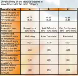
Table B: Dimensioning of low impulse systems in accordance with the room category
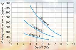
Fig 1: Room Category Comfort chart for low impulse system- cooling
This air movement will entrain room air and the two will mix but still continue to move downwards.
By the time the air reaches the occupied zone, at head height, the supply air will be mixed with the room air by approx 65 to 80%.
The cooling temperature differential and the amount of supply air per metre of duct not only effects the degree of mixing but also determines the velocity of the air in the occupied zone and the temperature immediately below the duct in the occupied zone.
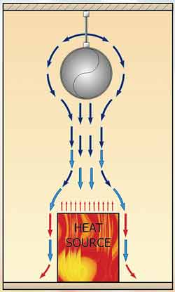
Fig 2: Normal room heat distribution
Fig 2 shows cooling air distribution for normal heat load in situations where a very even temperature is required across the plan of the area resulting in a very homogeneous conditioned environment.
Fig 3 shows what can happen if the heat source is of a considerable size and the result of which is that the falling cooling air currents ‘ricochet’ off the rising heat convection currents.
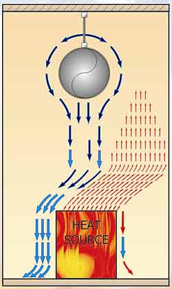
Fig 3: the conflict between a very high heat source and low impulse
This can cause draught as all the cooling air falls to one side of the heat source. The way in which this can be over come, is to have the low impulse ducts to one side of the heat source and in this way the cooling air then displaces the warm air.
This equates to an efficient set up whereby 1kW of cooling may overcome 1.5kW of heat load.
“D” semi circular textile ducts as opposed to the full circular ducts are used in applications where the headroom is limited, say to 3,000mm, or when 100% turn down is required on a variable air volume basis.
The full circular type can accept a turn down in volume of up to approx. 60% of the full volume providing that the system is designed with this in mind, as the static pressure in the furthest runs of textile ducting must remain at approx. 60Pa.
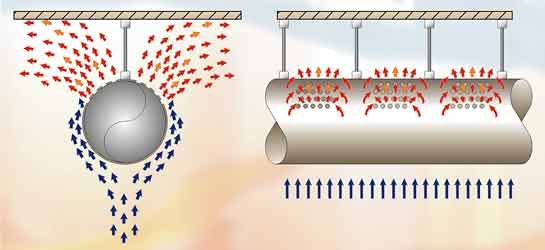
Fig 4: air flow around a high impulse duct - mixing and induction
High Impulse
The supply air jets out of the specific pattern of holes at between 10m/sec and 15m/sec depending on design parameters and without noise irritation.
The system has the ability to draw in 20 to 40 units of room air relative to 1 unit of supply air, this rated at a distance of 3,000mm away from the duct. To provide a comparison, a traditional nozzle draws in 12-15 units of room air relative to 1 unit of supply air.
The high velocity of the air through the patterned holes provides the momentum for the system to push the air across the room and down into the occupied zone, even when the holes are uppermost or pointing in the directions of 3 o’clock and 9 o’clock.
The supply air soon becomes mixed with the drawn-in room air, see fig 4, a braking action takes place and by the time the mixed air enters the occupied zone it will have slowed down significantly so that the specified comfort conditions are achieved.
Whilst this air is being pushed, the high discharge velocity is drawing air to flow upwards from the occupied zone by the ‘Venturi Action’ since a low pressure is created below the duct. The two air movements meet and a room air circulation is set up creating a very homogeneous room environment, see Fig 5.
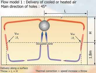
Fig 5
Low air movement is rarely more critical than in a swimming pool hall, as the wet bathers are very susceptible to draught and too higher an air movement over the pool water will lead to higher rates of pool water evaporation. Air movements around the poolside and above pool water should be around 0.1m/sec
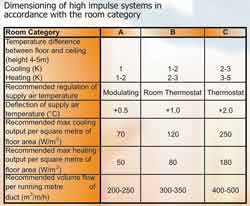
Table C: Dimensioning of high impulse systems in accordance with the room category
With thanks to Mike Creamer of Business Edge who revisits his Masterclass series of articles, updating and adding to the information which proved so useful to readers when the series was first published over ten years ago. In this reincarnation, the series will cover both air conditioning and refrigeration and serve as an on-going source of technical reference for experienced personnel as well as providing a solid educational grounding for newcomers to our industry.