Most chiller manufacturers insist on the installation of a paddle type flow switch to protect the evaporator against loss of chilled water flow.
This must be installed properly in a straight length of pipe in accordance with the switch manufacturer’s instructions. The use of a pressure differential switch in place of a flow switch will void the vessel guarantee. For those evaporators operating with either R22 or R407C where water is the chilled media, a minimum saturated suction pressure of 3.5bar gauge must be ensured via the use of a pressure switch or microcomputer/ pressure transducer combination. A minimum saturated suction pressure of 1.7bar applies in the case of R134a evaporators. A minimum chilled media temperature of 3.3°C is permitted, where water is the chilled media. For glycol solutions, a minimum solution temperature 3.3°C above the freezing temperature of the glycol concentration is permitted.
These limits, in combination with the use of a flow switch, ensure that there is no danger of evaporator freezing. When R407C is used, a minimum mean evaporation temperature of 2.5°C is used during evaporator selection to compensate for the glide in the evaporator. This prevents nuisance time-delayed low pressure trips and provides further protection against freeze up.
Water quality
Once installed in a packaged water chiller, there is a need to ensure proper control of water quality on site. The services of a local water treatment specialist may be justified in order to maintain a neutral pH value on the waterside of the vessel. The use of brines may require the use of special evaporator materials. In particular, the use of calcium chloride on the chilled media circuit should be checked with the manufacturer before ordering.
Shell and tube evaporators will occasionally require cleaning. Where the tube bundle may have to be removed or repaired it is essential to ensure that adequate space exists on site to facilitate withdrawal and re-insertion of tubes, an entire bundle or cleaning rods.
Chilled water flow pumps
Two pumps are normally installed; one for normal running operation (run) and one to bring into operation should the run pump fail (standby). When designing a chilled media circuit, the constant flow pump should always be located to discharge into the evaporator inlet spigot, downstream of a 40-mesh strainer.
Evaporator anti-freeze protection
To reduce the possibility of freeze up, the chilled media pump starter, flow switch contacts and anti-freeze thermostat should be electrically interlocked with the chiller control panel, so that if any of these detects a flow failure, each compressor is immediately stopped. Many DX evaporators are not provided with sockets to permit the installation of suction pressure relief valves, but a relief valve or valves should be included in the suction piping of the chiller unit, to comply with the European standard, and to protect the evaporator against over-pressurisation by unqualified site personnel during the commissioning process. This has been known to be particularly important if the hot and cold water piping circuits become accidentally crossed during system installation.
Refrigerant flow control
The variation of refrigerant flow and consistent close control of superheat in DX evaporators has a dramatic effect on their performance. The use of electronic expansion valves offers a number of benefits. By pushing the refrigerant liquid dry out point (where all liquid refrigerant has evaporated and superheat begins) nearer to the suction end of the evaporator, more tube surface is used for evaporation and less in achieving the suction superheat necessary to protect the compressor against liquid slugging. This is only possible if the expansion valve control system is both sufficiently well advanced and correctly commissioned. Another vital ingredient is the use of properly engineered refrigerant distribution systems within the evaporator. The use of mild steel angle to create a splash plate is considered insufficient to create a homogenous liquid/gas mixture of equal quality across the inlet tube plate. Oscillations of the liquid dry-out point across the tube bundle cross section would prevent the expansion valve(s) from maintaining a consistently low suction superheat.
Electronic expansion valves incorporate the use of pulsed solenoid valve devices to provide a reliable means of minimising suction superheat while maintaining stable suction pressure and evaporating temperature. Rapid reaction to changes in evaporator/compressor load, and the ability to provide stable operation with low discharge/suction pressure differentials that allow efficient chiller operation at reduced head pressure are two advantages offered by this control technique. The pulsed nature of the flow leads to a high level of refrigerant turbulence in the evaporator refrigerant inlet plenum, further improving distribution, thermal performance and oil return. Additionally, the electronic control system allows the rapid alteration of refrigerant type, eliminating the need to change thermostatic elements within a wide capacity range whilst reducing package chiller manufacturers valve inventory.
Shell and tube direct expansion water chillers
Shell and tube direct expansion water chillers have the following advantages over other types of water chiller evaporators:
• Their design generally allows for oil to be entrained in the refrigerant gas for adequate return to the compressor without the need for complex and expensive oil return systems.
• At a cooling capacity of less than 1000kW they are generally smaller than flooded vessels.
• As a consequence of their simple oil management and compactness they are generally cheaper than flooded vessels below 1000kW capacity.
The disadvantages of shell and tube direct expansion water chillers are:
• Unless suitable filters are used upstream in the water circuit, and/or water treatment is employed where necessary, they can become clogged with water-borne solids which subsequently lead to a reduction in cooling capacity and the possibility of damage through freezing as a result of reduced water flow rate. The design of shell and tube direct expansion water chillers usually makes them suitable for cleaning by chemical methods only.
• The compact design of the tube bundles is one of the reasons for the relatively high efficiency attainable as a result of having low water/ brine contents in the shell. It is for this reason they have to the protected against damage through freezing by incorporating and accurately calibrating a high quality and reliable low-limit and freeze-protection thermostat. The capacity range for this type of water chiller can be from as low as 2kW up to 2000kW. However, for financial and practical reasons they tend to be limited to 1000kW with flooded shell and tube evaporators generally being used for larger capacities.
Refrigerants
Shell and tube direct expansion water chillers are generally suitable for use with the traditional CFC and HCFC refrigerants such as R12, R22, R500, R502, etc, as well as R134a and R717. They are suitable for use with the zeotropic refrigerant blends such as R407C although caution must be exercised when deciding upon operational parameters due to the varying temperatures at which the individual constituents of the blend evaporate, a phenomenon known as the glide factor. Flooded shell and tube evaporators, where the refrigerant is in the shell surrounding the tube bundle and the water/brine runs through the tubes, have already been covered in reasonable detail, but the advantages and disadvantages of these are now considered in relation to shell and tube direct expansion water chillers.
Advantages:
Higher efficiency than shell and tube direct expansion water chillers; above 1000kW they are generally more compact than shell and tube direct expansion water chillers and are therefore of lower cost; water/brine tubes are relatively easy to clean; the capacity range is much larger than DX (direct expansion) vessels, ranging from 1000kW to 6000kW; the refrigerant distribution difficulties associated with shell and tube DX water chillers, particularly on the second pass do not apply to the flooded design.
Disadvantages:
Oil is generally retained in the vessel on the boiling surface of the liquid refrigerant making oil recovery a more complicated and expensive affair; it is vital to ensure that only dry and adequately superheated refrigerant vapour leaves the evaporator for the purposes of compressor protection; the introduction of replacement zeotropic refrigerant blends types dictates that these should only be considered for use with flooded evaporators with extreme caution; the oil recovery and suction gas filtration requirements generally make them uncompetitive against DX vessels below 1000kW capacity.
Flooded shell and tube evaporators are normally suitable for use with the traditional CFC and HCFC refrigerants including R11, R12, R22, R113, R114, R123, R500 and R502 as well as R134a and R717.
Evaporator selection
In order to select an evaporator of the correct capacity for a given duty, the following criteria must be known:
• Required cooling duty: kW
• Chilled water inlet temperature: °C
• Chilled water outlet temperature: °C
• Chilled water flow rate: kg/s or l/s
• Refrigerant type
• Evaporating temperature: °C
• Saturated discharge temperature: °C
• Extent of sub-cooling: K
• Number of refrigerant circuits
Where an additive to the water for anti-freeze purposes is involved, the type must be known together with the degree of concentration as this causes a variation to the value of several physical properties of the solution including specific heat, thermal conductivity and viscosity. One single factor which affects the size and model selected for a given duty is the approach temperature. The approach temperature is the difference between the chilled water outlet temperature and the evaporating temperature. Within reasonable parameters, the larger the approach temperature the smaller the vessel required for a given duty.
In order to select a shell and tube direct expansion water chiller utilising normal selection tables, the following procedure applies:
• Calculate the chilled water range (inlet temperature - outlet temperature)
• Calculate the approach temperature (chilled water outlet temperature - evaporating temperature).
• Locate the selection table for the calculated chilled water range and then plot the required cooling duty against the approach temperature to obtain the vessel which must closely matches the requirement.
• Calculate the design water flow rate (kg/s or l/s) using the following equation:

Where:
Q = design cooling capacity: kW
T1 = entering water temperature: °C
T2 = leaving water temperature: °C
Cp = specific heat of water - 4.187 kJ/kg K
kg/s or l/s = design water flow rate - kg/s or l/s
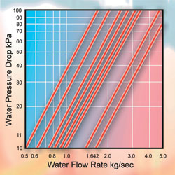
• Plot the design water flow rate onto the pressure drop curves for the selected vessel to ascertain the water-side pressure drop through the vessel.
• When an additive such as glycol is used, the revised specific heat of the solution must be used.
Shell and tube evaporator selection procedure
Two key factors which have a major influence on the performance of a the shell and tube dry expansion evaporator are:
• Cooling range (K) = water inlet temperature °C – water outlet temperature °C.
• Terminal temperature difference (K) (approach temperature) = water outlet temperature °C – evaporating temperature °C. The above therefore very often forms the basis of manufacturer’s capacity data for equipment selection purposes. Certain products provide the optimum performance when a temperature difference of at least 10K exists between the evaporating temperature and the water inlet temperature, very often defined as the superheat approach temperature.
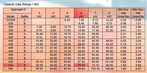
Selection example:
The essential information that will always be required includes: evaporator load in kW; evaporator water flow rate in litres/sec; chilled water inlet temperature °C; chilled water outlet temperature °C (any 3 of the above items will be required); evaporating temperature °C; single or dual refrigerant circuit evaporator required.
The above information will then allow a selection to be made. For example:
• evaporator load = 55kW
• evaporator water flow rate in l/sec (not given)
• chilled water inlet temperature = 16°C
• chilled water outlet temperature = 8°C
• evaporating temperature = 2°C
• single refrigerant circuit evaporator required
Step 1:
From the information, calculate the range and approach for your application. Range: 16°C - 8°C = 8 K Approach: 8°C - 2°C = 6 K
Step 2:
Refer to selection table example (above) which relates to a range of 8K and use the approach column for 6K, locating the model with a capacity most closely related to the requirement (select CH548B).
Step 3:
Calculate the design water flow rate from the following equation:

Step 4:
From the curves showing water pressure drop in relation to water flow rate, determine the water pressure drop for 1.642l/s from the graph above, right. (11kPa).
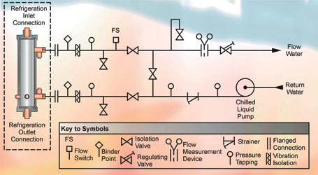
figure 1
Simple dos and don’ts for protection of evaporators in operation:
DO
• Check and maintain glycol strength regularly.
• Install a strainer in the water pipework immediately upstream of the evaporator.
• Install a flow switch in the water pipework downstream of the evaporator, interlocked with the safety controls governing the running of the compressor(s).
• Ensure the materials of construction of the evaporator are suitable for use with the fluid to be cooled.
• Ensure the evaporator is correctly sized to provide an adequate level of turbulent flow over the tubes to ensure good heat transfer (approximately 0.6m/s). Generally speaking, the lower the pressure drop, the lower the level of turbulent flow.
• Ensure the fluid to be pooled does not carry any small particles in suspension which could be trapped within the vessel leading to eventual blockage.
DON’T
• Use shell and to evaporator with a continuous pump-down cycle.
• Evaporate below 0°C without using a glycol solution of adequate concentration to ensure a freezing point below the minimum operating leaving water temperature.
• Reduce the fluid flow rate through the vessel below the design figure.
• Stop the fluid flow rate through the vessel prior to stopping the refrigeration system.
• Operate the vessel beyond the design parameters.
• Weld any items to the vessel shell without consulting the manufacturer.
• Set low limit and anti-freeze thermostats below the manufacturer’s recommendations.
Chilled water pipework
It is essential to install a variety of key components in conjunction with shell and tube DX water chillers in order to be able to commission the system correctly, maintain a check on performance and protect the chiller against freeze up due to inadequate water flow rate.
The following devices should therefore be included: flow switch; binder point (for measuring temperature); isolating valves (for service, repair and replacement); regulating valve (for balancing water flow rates to design levels); flow measuring device; strainer (for collection of particulate matter); pressure tappings; vibration isolators.
A typical arrangement for the positioning of the above items is shown in Fig 1.
NEXT MONTH: Part 17 Baudelot coolers and liquid receivers
With thanks to Mike Creamer of Business Edge who revisits his Masterclass series of articles, updating and adding to the information which proved so useful to readers when the series was first published over ten years ago. In this reincarnation, the series will cover both air conditioning and refrigeration and serve as an on-going source of technical reference for experienced personnel as well as providing a solid educational grounding for newcomers to our industry.