There are only a few manufacturers of GHP-based systems and in this article we will concentrate on Sanyo. I spent some time working on r&d into gas-engine driven heat pumps in the late 70s. However, Japan is the birthplace of GHP, where it was developed in the early 80s when the demands of Tokyo's 20 million population meant the national grid threatened to reach breaking point.
Sanyo supplies its European customers with GHP systems in the form of a two-pipe heating and cooling system, and three-pipe heat recovery, gas fuelled VRF system offering nine system types in five capacity sizes. The minimum operating ambient temperature conditions are -20°C for heating and -10°C for cooling. No defrost operation is required in the heating mode and there is no heating downtime to contend with.
Power supply for the GHP is single-phase and the actual electrical consumption is as low as 630 W, due to inverters. Either natural mains gas or LPG can be used to power the system.
All GHP models use Nissan engines which, with regular servicing, are said to offer approximately 13-years trouble-free operation. Major servicing is recommended at 10,000-hour running-intervals (3.2 years running - assuming 12 hrs x 5 days x 52 weeks).
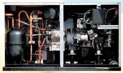
GHP outdoor units - engine components
To achieve the long service intervals offered by the GHP the engine requires two oil tanks. The larger oil tank of 30 litres is positioned between the outdoor heat exchangers, and a 5 litre sub-oil tank which is positioned below. There is also approximately 5 litres of oil contained within the engine sump.
The oil system has an external oil pump to circulate the oil from the sub-tank to the engine sump. The engine also has an internal oil pump just like a normal car engine.
Two air-cooled water coolant heat exchangers are positioned before the refrigerant air-cooled heat exchangers, which are of equal size. If the engine water rises above 80°C, then coolant water passes through these.
There are two water tanks installed. The main tank is installed at high level and the reserve tank is installed below. The coolant water is filled with water/glycol to prevent freezing with protection to as low as -45°C. The system's coolant water pump is an inverter-driven pump, operating on 240 V dc. Full speed is 3,200 rpm. The air intake filter is very similar to that found in a conventional car engine.
The GHP uses a special type of spark plug that has been designed for longer life. The same plug is used for all models.
Control of the gas/air mixture control valve or throttle valve is achieved by a step motor operating between 0-480 steps. The control valve is varied when higher/lower engine rpm is required.
The GHP exhaust/coolant water heat exchanger is of the shell and tube variety, acting as a condenser to condense the moisture from the exhaust gases. The exhaust gas chain neutraliser ensures that the moisture condensed from the exhaust gases is passed to the drain neutraliser. The drain neutraliser contains calcium carbonate chippings that absorb the acid produced, maintaining the drain water at a pH level between 6.8-7.0 (pure water has a pH value of 7.0).
The stainless steel exhaust muffler normally operated at 80°C. A high temperature muffler sensor is fitted to ensure that if the temperature exceeds 130°C, the high temperature alarm will be triggered.
A gas control valve in the system incorporates three jets, a fixed main jet, a fixed by-pass jet and a variable control jet. The valve also contains an adjustment plate that is used if the GHP is run on LPG.
GHP refrigeration system
The compressor used in the refrigeration system is a belt-driven multi-vane rotary compressor incorporating five vanes, two suction ports and two discharge ports. The lubrication oil used is polyalkaline type unique to the GHP.
Two outdoor heat exchangers are incorporated in the refrigeration system, both equal in size. The suction/coolant water heat exchanger used in the systems is a plate-type suction gas/coolant water heat exchanger that is used in the heating mode. Coolant water is passed through the exchanger to allow suction gas to absorb heat transferred from the engine. The water flow is regulated via a three-way control valve.
A hot gas bypass valve is in place to unload the compressor during start-up. It is also used to prevent low refrigerant pressure situations occurring. Two standard pressure transducers are fitted, one to the discharge line (for head pressure control) and one to the suction line for capacity control and system protection. These transducers enable the actual operating pressures to be viewed via the outdoor PCB.
Engine operation
When there is a requirement for cooling or heating from a single fan coil (the minimum size is 2.2 kW) or multiple fan coils, then the engine is started. At this point the engine rpm is governed by the difference between the temperatures set-point and the actual current operating temperature. Therefore, the greater temperature difference, the higher the engine rpm. The minimum operating engine speed is 800rpm and the maximum speed is 2,200 rpm. When there is no need for cooling or heating from any of the indoor units, the engine stops.
To achieve the 10,000 hour service intervals, the oil system has been developed to automatically top-up, as required. Float switches situated in the sub-oil tank enable this function to take place. The float switches open a double solenoid valve in the oil supply line from the main high-level oil tank, therefore allowing oil top-up as required. The engines are expected to use oil at a rate of 3cl/h.
To increase the flexibility and usage of the GHP, a water chiller can also be installed. The water chiller can be positioned up to 120 m from the outdoor unit, making internal location possible.
The operating range for chilled water is +5°C to +25°C as standard. If required, the system can provide hot water with a temperature range from 25°C to 55°C
Simple local control at the water chiller is a standard feature. A remote control option is also available, allowing remote stop/start and alarm functions.
The larger outdoor units can be supplied with an additional internal heat exchanger. This allows for external hot water to the supplied whenever the GHP unit operates in the cooling cycle. Instead of dissipating engine heat to atmosphere, the engine cooling water is passed through the internal heat exchanger and this heat is then passed into a secondary water system. Up to 22 kW of heat energy can be produced at a temperature of 75°C, making this option a viable means for boosting the performance and temperatures of any existing hot water system. While further developments have included a 4 kW generator whivh delivers 300 V dc power and is converted to 240 V single-phase via power inverters.
Commissioning
After completing the installation of interconnecting and supply wiring and piping, the GHP utilises a simple automatic address procedure for the indoor and outdoor units (no need for any DIP switch settings) which allows for quick system set-up.
On completion of the auto address procedure, system operation is then possible. Operation of the GHP is then monitored, ensuring all run conditions are within normal operating parameters. To assist in collating the running date the Sanyo service checker can be connected. After recording the running conditions, this information can then be stored and printed for insertion within the commissioning documentation.
Service/maintenance requirements
The following are required when carrying out a 10,000hr service.
1) Change all oil
2) Change oil filter and oil blow by filter
3) Change air intake filter
4) Change spark plugs
5) Change drain neutraliser crystals
6) Engine inspection including compressor drive belt
VRF specification
When specifying or applying a VRF system the main criteria are often based upon three main factors, these being:
· Cooling and heating capacity requirements;
· Indoor and outdoor unit size and style;
· Basic control function
Often after the project has been completed changes or 'system tweaks' are required to meet the final clients needs. With the Sanyo Eco-Multi systems there are many options available that can be utilised to obtain the desired goal.
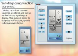
The RCS-SH80BGremote controller forms the basic control requirements for the SPW commercial range of equipment (both split systems and VRF). As well as being a wall-mounted remote controller, it also doubles as a service tool. When commissioning or servicing VRF equipment access to actual real-time operational data is useful, this can give an insight into the condition of the current operational system and ensure that the system is in an optimum running condition. When the RCS-SH80BG controller connected to the indoor unit, sensor data can be accessed.
These include indoor unit return air and supply air temperatures, indoor heat exchanger temperature valves and expansion valve opening position. Access to the connected outdoor unit is also available. This allows the outdoor coil temperatures, compressor running currents and condensing units expansion valve positioning to be viewed.
Armed with this information, the engineer can save a great deal of time. In the past, logging all this data meant manually taking the temperature readings at each different point and in the case of the internal heat exchangers this was virtually impossible.
Apart from local control at each indoor unit, there is often a need for a master controller to be installed within a system to allow remote access from a central point. The SHA-KC64AGB system controller can control up to 64 groups of indoor units, allowing the same level of control functions that are available from a local controller.
Also available within the system controller is the facility for external control link ups. These include remove system on/off, operation and alarm outputs. With these facilities simple time clocking o the system is easily achievable and remote alarm signalling and operation status, this feature can be used to switch on any remote fresh air fan or auxiliary equipment, allowing the control to be fully interlocked.
Software control
To complement any large VRF installation, the requirement to control the whole installation from a computer becomes a necessity for many facilities managers or building services managers. Not only can the whole system be checked to ensure all is well but by utilising a computer control systems, remote access via a modem, the internet, or even a mobile telephone is now possible.
The AMY software package can operate from any computer running Windows-based software and by connecting to the Sanyo network up to 2,048 indoor units can be controlled. The level of control that the AMY control system offers includes, remote start/stop, time clocking including daily and weekly functions, room temperature values, alarm notification and history. To prevent or limit local user changes, the facility to prohibit the remote controller operation can also be set. This option comes with three levels of lockout allowing the facilities manager to have even more control of his installed system.
Individual user billing is also available via simple indoor unit run-time indication.
Optional function switching
Various control options are available as standard on the SPW range of indoor units. Being simple pluggable sockets on the indoor unit PCB, allows for a number of control options.
The most common usable connection point is the T10 socket. This offers a remote stop/start facility, via external volt-free contacts. This could be contacts on a simple time clock, or contacts on a BMS control system. Also available on the T10 socket are two 1.2V dc outputs. These can be used to monitor indoor unit operation an indoor unit alarms. Connection can be back to a remote monitoring panel or BMS system.
For safety, air conditioning systems need to be connected to a fire shutdown panel. To achieve this once again is a simple connection point on the indoor PCB, this time CN10 is used. Volt free connections to the fire panel if closed force the indoor unit to shut down. After resetting, the fire shutdown panel allows for a manual restart of the system.
To complement the Sanyo three-pipe heat recovery system, the indoor PCB has the facility to connect a refrigerant leak detector, using connection point EXCT via volt-free connections will in the event of a closed set of contacts force the whole system to shut down and generate a dedicated P14 alarm. This alarm also shuts down a 240 V pair of contacts at the outdoor unit thus allowing a set of field supplied motorised valves to be driven closed to isolate the outdoor unit.
Detailed setting modes
As mentioned earlier, the RCS-SH80BG remote controller doubles as a service tool. With one of these connected to a SPW indoor unit, further functions can also be accessed.
A key concern of many air conditioning systems is the potential for users to turn the temperatures to the lowest setting and leave it set at this point even though they may have let the office space. Not only is this a waste of energy but unnecessary system wear and overloading can occur.
To overcome the above, accessing the Detailed Setting mode gives the facility to limit the temperature control set points. Not only is this offered for the cooling mode, but applies to heating auto and dry modes. Temperature control ranges can therefore be restricted to meet the client's requirements. An ideal temperature control span could therefore offer 20-24°C in cooling mode, and say 22-26°C in the heating mode, but if a fixed set point is also required, then this can also be offered, for example within a communications or computer room to control at cooling 20°C.
Also within the detailed setting mode, there is the facility to adjust the temperature control of the supply air temperatures within the ducted style units. As standard these units aim to limit the supply air temperature to 12°C in the cooling mode, and a maximum supply temperature of 50°C in the heating mode. Having the facility to adjust this supply air setting between 7-20°C in the cooling mode enables the system to be applied to sensitive areas where cold air dumping creates a problem.
External BMS systems
The level of control that is currently offered by specialist third party systems is now quite exceptional and is covered in great detail in previous Masterclasses. However, suffice to say that Sanyo offers integration into all the major systems via gateways (protocol converters) such as Lonworks or Compass Nodes to name but two. This facility, although very important to offer, is less frequently taken up due to the additional costs from the specialist controls company.
Conclusion
Having discussed the various control options available with the VRF systems enables final system tweaking to the easily achieved. If the facility requirements of the conditional space change, then simple no cost adjustments can be made.
If optional time clocking or alarm monitoring is required, no additional PCBs have to be obtained and installed, having these facilities as standard means no cost future flexibility can be catered for without the need for potential expensive additional budgeting.
With thanks to Mike Creamer of Business Edge who revisits his Masterclass series of articles, updating and adding to the information which proved so useful to readers when the series was first published over ten years ago. In this reincarnation, the series will cover both air conditioning and refrigeration and serve as an on-going source of technical reference for experienced personnel as well as providing a solid educational grounding for newcomers to our industry.