Although by no means a new concept in providing comfort cooling, the static cooling device has enjoyed resurgence in popularity with designers of cooling systems in the UK.
Two primary categories of static cooling device exist: chilled ceilings and chilled beams.
Chilled ceilings
Chilled ceilings generally take the form of a flat panel with a pipe coil attached to one side. Chilled water is circulated through the pipe coil. The chilled water absorbs heat from the flat panel, which in turn absorbs heat from the space. The flat panel is usually located flat side down on the ceiling of the space; hence the name chilled ceiling.
Chilled beams
A chilled beam is a variation of the chilled ceiling. Essentially the chilled beam is the cooling equivalent of the trench heater. Flat fins are attached to a chilled water pipe. An aluminium plate often encases each of the two sides of the assembly, and the bottom is either encased with an aluminium plate with slots or an egg-crate grille.
The resulting unit is located at high level in the space and resembles a beam, giving the name chilled beam. Chilled beams can be further sub-divided into two categories: passive or active. The active chilled beam additionally has a ducted supply of primary air connected to the top of the unit. The addition of the primary air increases cooling capacity and provides a mechanism for introducing outside air to the space.
History
The earliest form of static cooling is the use of the thermal mass of the building. Ancient civilisations such as the Incas, Egyptians and Aztecs utilised high thermal mass materials in their building structures. Throughout history, these high thermal mass materials were used, sometimes also in conjunction with running stream water to provide a constant source of cooling, examples of which include the atrium of the ancient Pompeian house and the al fresco dining terrace in the garden of Villa Lante in Bagnaia, Italy.
More recently, the mechanical cooling system of the 1,800,000ft2 Shell Centre on the South Bank of the River Thames in London, designed in 1953, is an early example of a mechanical static cooling system. Here, the cool water of the river is utilised as the condenser water source with cooled water circulated through flat ceiling mounted radiant panels.
The most recent swathe of static cooling installations in the UK was inspired by projects in Scandinavia originating in the 1980s. The first design projects reached the UK in 1989 and the first chilled beam installation in the UK was commissioned in the early 1990s.

Fig 1: Passive beams

Fig 2: Passive beams
Since the first UK installation of chilled beams, numerous other buildings have been designed using either chilled beams or a chilled ceiling. Product developments have been numerous and a simple keyword search on the Internet will identify a fistful of product manufacturers. Not only have the products evolved, but the refinement and broadening of their application has also occurred as the number of installations increased.
Both the chilled ceiling and the chilled beam provide sensible cooling only to the space. Sensible heat exchange within occupied spaces typically takes two forms: radiation and convection.
Heat exchange by radiation occurs when a temperature difference exists between two surfaces that can see each other. Heat radiation is long-wave electro-magnetic oscillation and, as such obeys the same laws of physics as light rays - it travels in a straight line, travels through air, is reflected in part by a surface and is absorbed in part by a surface. Only surfaces emit thermal radiation and the amount of energy emitted by a surface increases with the 4th power of its absolute temperature.
Heat exchange by convection falls into two categories: natural (free) convection or forced convection. Natural convection occurs when a temperature difference occurs between a surface and the air in contact with the surface.
When the surface is cooler than the adjacent air, the air is cooled, becomes more dense than the surrounding air and falls under gravity. When the surface is warmer than the adjacent air, the air is warmed, expands and becomes less dense than the surrounding air which in turn falls under gravity, pushing the warmed air upwards. With forced convection, the motive power for the air movement is not the temperature difference, but rather a mechanical force such as a fan.
Chilled ceilings provide cooling to the space via both radiant heat transfer and natural convection. With the chilled ceiling, the primary mechanism for heat exchange is by radiation, although convective heat transfer does account for almost 50% of the cooling.
With the chilled beam, convective heat transfer is dominant, accounting for approximately 85% of the heat transfer. Cooling capacities of both the chilled ceiling and the chilled beam depend on numerous factors such as: chilled water flow/return temperatures, room air temperature, room mean radiant temperature, and location of unit.
Maximum cooling capacities are, however, usually in the ranges given below:
Chilled ceiling: 50W/m2 - 100W/m2
Passive chilled beam: 100W/m2 - 150W/m2
Active chilled beam: 150W/m2 - 350W/m2
Mechanics
The chilled water pipework is usually either of plastic or copper and attached to the rear of the flat panel. The panel itself is commonly made of either metal or a plaster composite material.
The physical attachment of the pipe and the panel has attracted much research by manufacturers and an improved contact factor between pipe and panel does indeed provide superior heat exchange. The physical heat exchange from the space to the panel is via a combination of convective flows and radiation, whilst the heat flows from the panel to the pipe through conduction.
Ultimately the chilled water flowing in the pipe removes the heat from the device. Most manufacturers recommend a target water velocity of 1m/s to ensure that the water flow is fully turbulent to increase heat transfer.
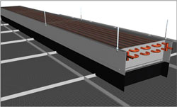
Fig 3: Recessed passive beams
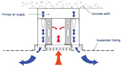
Fig 4: Active beams
A single loop of chilled water pipework forms the core of the device. The pipework of the chilled beam is usually of copper and has metal fins (usually aluminium) attached perpendicular to its length.
The casing to the beam typically consists of either three or four panels. In the uncapped chilled beam, the top of the beam is open, allowing air from above the unit to enter. Conversely the casing of the capped chilled beam includes a panel across the top of the unit, sealing it from the air above. The physical heat exchange in each case is similar, with the heat in the air adjacent to the aluminium fins being absorbed by the fins. The heat then flows from the fin to the pipe through conduction.
Finally the chilled water removes the heat from the pipe also through conduction. Turbulence of the water flowing through the pipe is again an important aspect of the heat transfer achieved, so the recommended velocity of the water is 1m/s.
With the active chilled beam, the heat transfer between the air and the fins is forced convection resulting in higher heat transfer. Air velocities exiting from the chilled beam are higher than those from a passive chilled beam.

Fig 5: Exposed active beams
Application
The primary design drivers for utilising a static cooling system are usually a mixture of the following:
· High levels of occupant comfort
· Energy (and cost) efficiency
· Reduced distribution space for mechanical services when compared with all air systems
· Low maintenance when compared with fan coil unit installations
· Quiet operation
As the above benefits can be realised, the type of project suitable for static cooling is varied, but the most common application is that of the office space, meeting rooms and associated areas in a commercial office building. With the commercial office building, the pressures to maximise thermal comfort, reduce running and capital cost, reduce building height with reduced distribution zones and reduce the maintenance schedule are great. The beneficiaries of utilising static cooling are numerous; however, the inherent resistance to deviate from tradition and some technical questions has restricted the take-up of static cooling in the UK building stock.
Whilst the quiet operation of a static cooling system is often appealing, the design team should assess the risks associated with specifying and installing a system that is in practice too quiet. Whilst the noise generated by an old or badly maintained fan located within alternative systems will cause a distraction, that very same component actually generates useful background noise for the majority of its working life. Therefore, in certain applications, a static cooling system needs to be used in conjunction with a white or pink noise system to mask private conversation.
The consequences of condensation forming on the chilled surface of both the chilled ceiling and the chilled beam and falling into the occupied space is a major concern for any designer of a system.

Fig 6: Multi service chilled beams
Numerous manufacturers of the cooling units have completed research into the subject along with control system manufacturers and BSRIA. The findings of the research indicate that for typical internal design conditions of 22°C ±2°C, 50% ± 20% RH, a chilled water flow temperature of 17°C will result in minimal risk of condensation droplets falling into the occupied space.
A risk assessment should, however, be carried out to assess how critical the operation or equipment is in the occupied zone and what the risk is, of either the room conditions or the chilled water temperature being outside of the expected range (a window being opened, or a valve actuator failing). If appropriate, a safety cut-out system can be designed. Such a system can take the form of either shutting off the supply of chilled water to the unit, or of mixing the return water to raise the flow temperature of the chilled water.
Whilst the location of a chilled ceiling is not critical - providing that it is located flat side down and generally above the occupants, the location of a chilled beam is more important. The chilled beam can be located either flush to a suspended ceiling system or exposed below the soffit. Performance is slightly increased if the chilled beam is located below the soffit as the radiant cooling effect is increased, as is the air circulation through the beam.
As the ceiling is often one of the most congested building components in a commercial office building, providing a location for lighting, smoke detectors and temperature sensors the addition of a chilled beam to the equation often provides a co-ordination challenge.
Although the air velocities of the air falling from a passive chilled beam are measurable, they are still comparatively weak compared to the air velocities formed by the rising plume of air from a hot window. If a passive beam is located adjacent to a hot window, the risk of the beam stalling exists. Evidently this presents a dilemma to the design team: the location most requiring cooling is unable to accept a passive chilled beam.
However, if an uncapped beam is utilised adjacent to the hot glazing, the perimeter-ceiling void can be utilised to form a channel. The rising plume is then directed to the top of the beam rather than the bottom, providing a driving force for the heat exchange rather than a restriction.
The control of the cooling output from the chilled ceiling and the chilled beam is approached in an identical manner. The cooling device inherently has a high degree of self-control. The self-control is due to the fact that the primary driving force for the heat exchange (either radiant or natural convection) is the temperature difference between the room and the device.
The difference of the surface temperatures is the driving force for the radiant exchange and the difference of the air temperature and the device surface temperature is the driving force for the natural convection. Therefore, as the cooling requirement increases on the space, so do the air temperature and the room surface temperatures. As the room temperatures increase, the amount of heat absorbed by the cooling device increases.
Similarly, as the cooling requirement of the space reduces, so does the amount of heat absorbed by the device. Instances of self-control from 15% to 100% of total cooling capacity have been reported for chilled beams.
Clearly operator control is also required, usually in the form of two-port on/off control valves, used to isolate the cooling device when not required. The two-port control also helps to increase the energy efficiency of the system by reducing the pumping costs of the installation.
A simple installation may utilise occupant control with a wall mounted on/off switch, although most installations tend to utilise a central BMS. The sensor location for the automatic control system can be either in the return air path or, preferably in the occupied space.
Summertime control set points for a static cooling system tend to be higher than in a comparable all-air system, as the BMS sensor is usually of the air temperature type.
Unlike the air temperature sensor, the occupants of the space are affected by the lower mean radiant temperature in the room, therefore, not requiring as low an air temperature to achieve the same levels of thermal comfort. The ability to control to a higher space air temperature also helps to reduce the running cost of the system.
Static cooling devices require a remarkably low amount of routine maintenance, as the number of moving parts is limited to the control valve. Therefore, when compared to other systems such as fan coil units that have a fan, a filter and control valves, the routine maintenance schedule is greatly reduced.

Fig 7: High induction active beam
Summary
Chilled beams and the chilled ceiling have proved themselves to be viable alternative to both central plant ac systems and the fan coil unit.
The primary advantages of using the system are:
high levels of occupant comfort; high Energy efficiency; low maintenance; reduced distribution zone for mechanical services; and quiet operation.
Some potential downfalls of the system are, however: condensation risk and reduction of speech privacy. These potential downfalls can be avoided by careful system design. As with most design challenges, an awareness of the issues at stake enables the designer to propose a solution.
Many thanks to Terry Farthing of Trox Technik for his help with the article.
With thanks to Mike Creamer of Business Edge who revisits his Masterclass series of articles, updating and adding to the information which proved so useful to readers when the series was first published over ten years ago. In this reincarnation, the series will cover both air conditioning and refrigeration and serve as an on-going source of technical reference for experienced personnel as well as providing a solid educational grounding for newcomers to our industry.